DocID024597 Rev 5 381/1830
RM0351 Chrom-Art Accelerator™ controller (DMA2D)
391
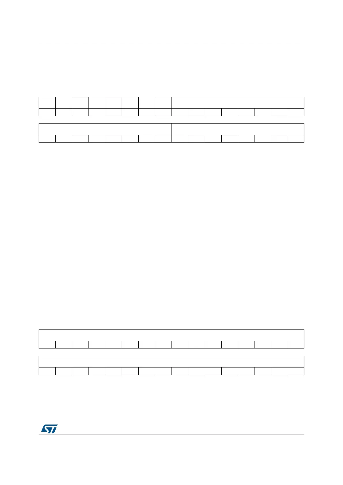
12.5.11 DMA2D background color register (DMA2D_BGCOLR)
Address offset: 0x0028
Reset value: 0x0000 0000
12.5.12 DMA2D foreground CLUT memory address register
(DMA2D_FGCMAR)
Address offset: 0x002C
Reset value: 0x0000 0000
31 30 29 28 27 26 25 24 23 22 21 20 19 18 17 16
Res. Res. Res. Res. Res. Res. Res. Res. RED[7:0]
rw rw rw rw rw rw rw rw
1514131211109876543210
GREEN[7:0] BLUE[7:0]
rw rw rw rw rw rw rw rw rw rw rw rw rw rw rw rw
Bits 31:24 Reserved, must be kept at reset value
Bits 23:16 RED[7: 0]: Red Value
These bits define the red value for the A4 or A8 mode of the background. These bits
can only be written when data transfers are disabled. Once the transfer has started,
they are read-only.
Bits 15:8 GREEN[7: 0]: Green Value
These bits define the green value for the A4 or A8 mode of the background. These bits
can only be written when data transfers are disabled. Once the transfer has started,
they are read-only.
Bits 7:0 BLUE[7: 0]: Blue Value
These bits define the blue value for the A4 or A8 mode of the background. These bits
can only be written when data transfers are disabled. Once the transfer has started,
they are read-only.
31 30 29 28 27 26 25 24 23 22 21 20 19 18 17 16
MA[31:16]
rw rw rw rw rw rw rw rw rw rw rw rw rw rw rw rw
1514131211109876543210
MA[15:0]
rw rw rw rw rw rw rw rw rw rw rw rw rw rw rw rw
 Loading...


