Digital filter for sigma delta modulators (DFSDM) RM0351
724/1830 DocID024597 Rev 5
or
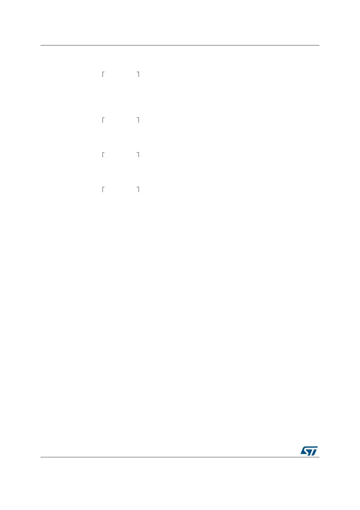
Maximum output data rate in case of parallel data input:
or
or
Note: ADC inputs are available for STM32L496xx/4A6xx devices only.
The right bit-shift of final data is performed in this module because the final data width is 24-
bit and data coming from the processing path can be up to 32 bits. This right bit-shift is
configurable in the range 0-31 bits for each selected input channel (see DTRBS[4:0] bits in
DFSDM_CHyCFGR2 register). The right bit-shift is rounding the result to nearest integer
value. The sign of shifted result is maintained - to have valid 24-bit signed format of result
data.
In the next step, an offset correction of the result is performed. The offset correction value
(OFFSET[23:0] stored in register DFSDM_CHyCFGR2) is subtracted from the output data
for a given channel. Data in the OFFSET[23:0] field is set by software by the appropriate
calibration routine.
Due to the fact that all operations in digital processing are performed on 32-bit signed
registers, the following conditions must be fulfilled not to overflow the result:
FOSR
FORD
. IOSR <= 2
31
... for Sinc
x
filters, x = 1..5)
2 . FOSR
2
. IOSR <= 2
31
... for FastSinc filter)
Note: In case of filter and integrator bypass (IOSR[7:0]=0, FOSR[9:0]=0), the input data rate
(f
DATAIN_RATE
) must be limited to be able to read all output data:
f
DATAIN_RATE
≤ f
APB
where f
APB
is the bus frequency to which the DFSDM peripheral is connected.
24.4.14 Signed data format
Each DFSDM input serial channel can be connected to one external modulator. An
external modulator can have 2 differential inputs (positive and negative) which can be
used for a differential or single-ended signal measurement.
A modulator output is always assumed in a signed format (a data stream of zeros and
ones from a modulator represents values -1 and +1).
Datarate samples s⁄
f
CKIN
F
OSR
I
OSR
⋅
----------------------------------
= ...FAST = 1
Datarate samples s⁄
f
DATAIN_RATE
F
OSR
I
OSR
1– F
ORD
+()F
ORD
1+()+⋅
----------------------------------------------------------------------------------------------------------
= ...FAST = 0, Sincx filter
Datarate samples s⁄
f
DATAIN_RATE
F
OSR
I
OSR
1– 4+()21+()+⋅
-----------------------------------------------------------------------------------
= ...FAST = 0, FastSinc filter
Datarate samples s⁄
f
DATAIN_RATE
F
OSR
I
OSR
⋅
----------------------------------- -
= ...FAST=1 or any filter bypass case F
OSR
1=()
where: f
DATAIN_RATE
...input data rate from ADC or from CPU/DMA

 Loading...