SUPPLEMENT S2
Chapter 3 – Airplane General Description
MECHANICAL SYSTEM
The mechanical system allows the pilot on the left seat to operate the rudder and the
throttle with the right hand. It is composed by an actuation handle terminating with a
joint and coupled with a detachable bushing, a series of supports and links to connect
the handle to the throttle and directional control of the standard configuration. The
longitudinal movements of the handle are transmitted to the left rudder pedal. The
angular movements of the handle are transmitted to the engine control via a bowden
driven wire.
The entire system is fastened to the fuselage structure through a support welded to the
truss of standard configuration (Figure C-3).
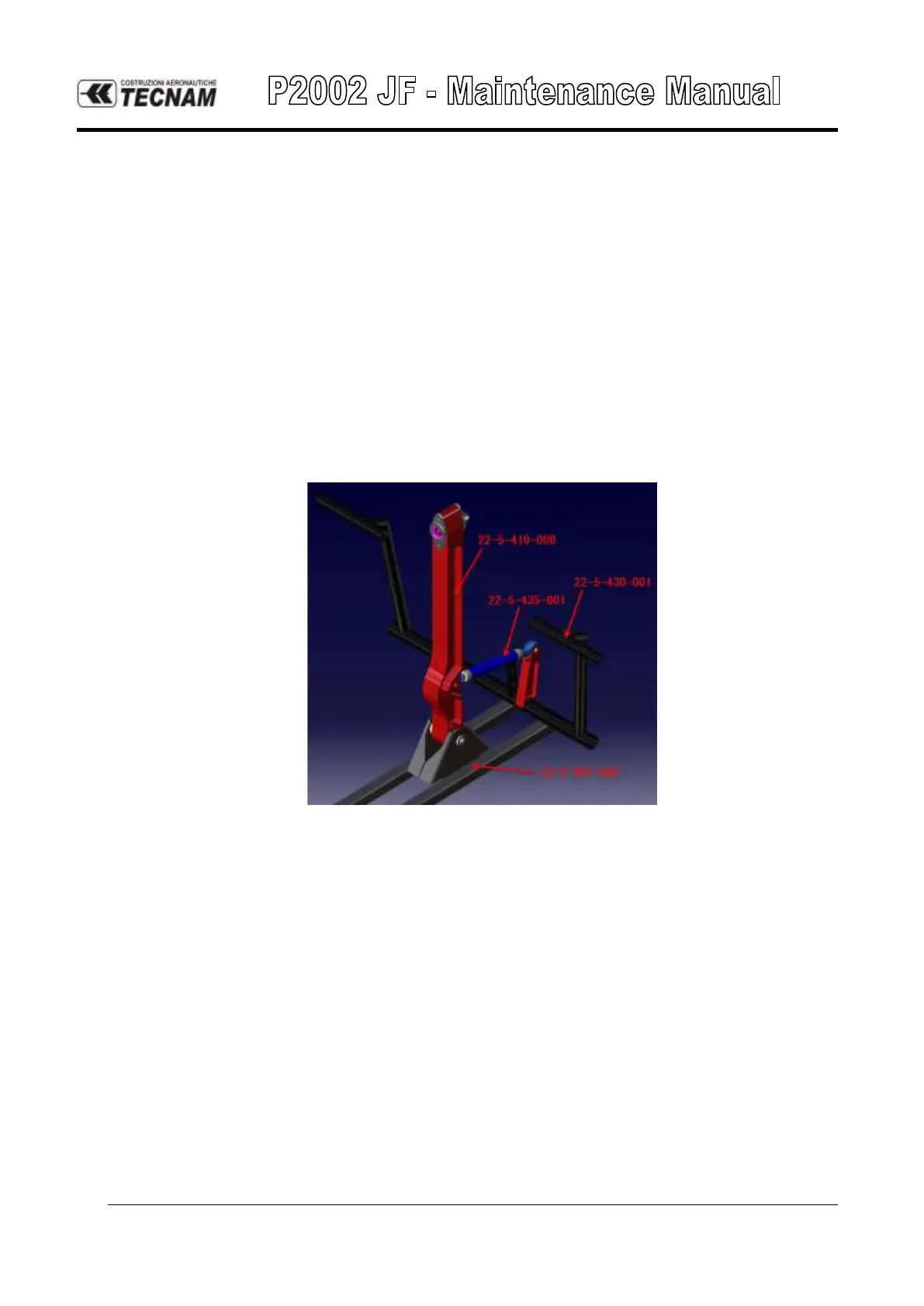
On the assy p/n 22-5-403-000 previously welded to the truss, is installed the assy 22-
5-410-000, which, through the assy 22-5-435-001 (control rod), is connected to
pedals (Figure A-5).
FIGURE 3-5 CONTROL COLUMN / PEDALS CONNECTION
In order to make the disassembling of the central hand control group easy, the
configuration features:
• The brake pump is installed on the LH stick to avoid, during the hand control
disassembly, also disconnecting of the braking system tubes; this installation is
described in this document and it is linked to MOD2002/146. There is no need to
disconnect this additional brake lever when disconnecting the central hand control
group;
• A mechanical interface p/n 22-5-445-000 (red round in Figure A-6) has been
introduced in order to allow the connection of removable hand control group. This
interface allows, through two AN3 (4.7mm diameter) bolts, a connection free from
free-play as the screws are assembled with 90° angle each other. The bolts used are
installed with nuts and cotter pins.