GENERAL FUNCTIONS TEEJET 5000 OPERATORS MANUAL
2.26
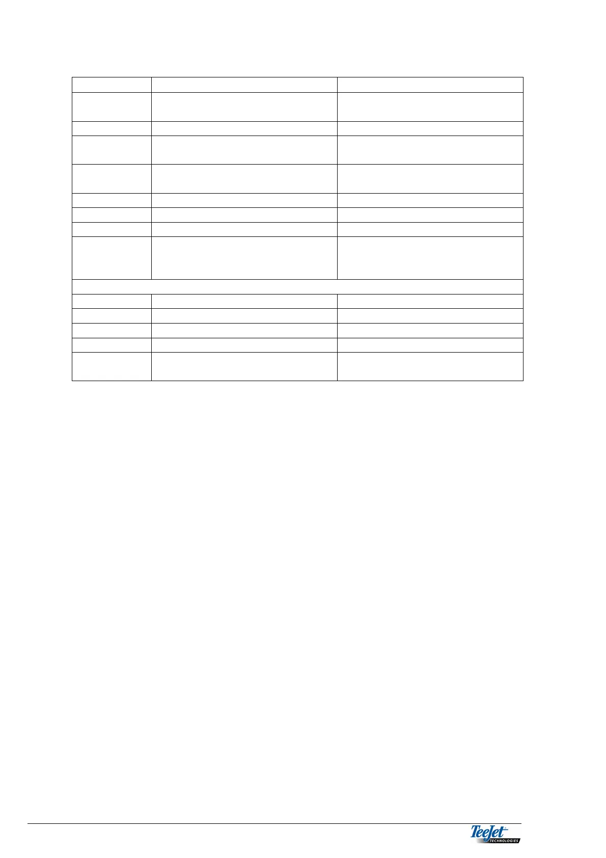
TEST INPUT RAUCH AXERA H
REI
β
L
TRAIL 1:
Signal from shaft speed sensor
(RPM 1).
Signal from RPM sensor fitted to
discs. (RPM 1)
TRAIL 2:
Not used. Signal from floor chain (RPM 2)
TRAIL 4:
Speed signal from trailed
implement.
Signal from speed sensor fitted
to the spreader.
TRAIL 7:
Area override on/off signal from
implement.
Area override ON/OFF from the
spreader.
TRAIL 8:
Not used. Not used.
TRAIL 15:
Not used. Not used.
TRAIL 16:
Not used. Not used.
BOM 1 – 12
Error is displayed as no boom
interface is connected.
Signal from individual boom
sections via system B (boom
section compensation), if used.
TEST OUTPUT
OUT 1:
Signal to close the gate (left). Signal to the regulating device.
OUT 2:
Signal to open the gate (left). Signal to the regulating device.
OUT 3:
Signal to close the gate (right). Not used.
OUT 4:
Signal to open the gate (right). Not used.
POT 1 – 2:
Shows the position of the
actuators.
Not used.