Procedure
Step 1
Connect the return cables of the power supply to the Earth ground located at the power supply side.
Step 2
Connect the office power according to the fuse panel engineering specifications.
Step 3
Measure and cut the cables as needed to reach the NCS 2002 from the fuse panel.
Step 4
Dress the power according to local site practice.
Step 5
Strip 1/2 inch (12.7 mm) of insulation from all power cables that you will use.
Step 6
Crimp the lugs onto the ends of all power leads.
Step 7
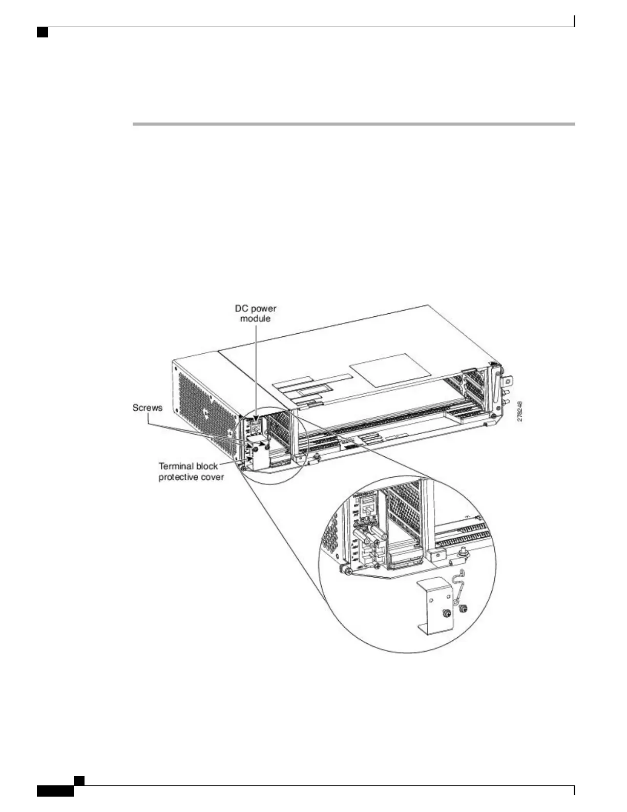
Verify that the DC power module is installed in Slot A.
Step 8
Remove the screws from the terminal block protective cover from the DC power module (see the figure
below).
Figure 46: Connecting Office Power
—
DC Power Module (ANSI Only)
Cisco NCS 2000 Series Hardware Installation Guide
86
Connecting Power and Ground
DLP-L50 Connecting Office Power (DC) to the NCS 2002 Shelf (ANSI Only)