Step 9
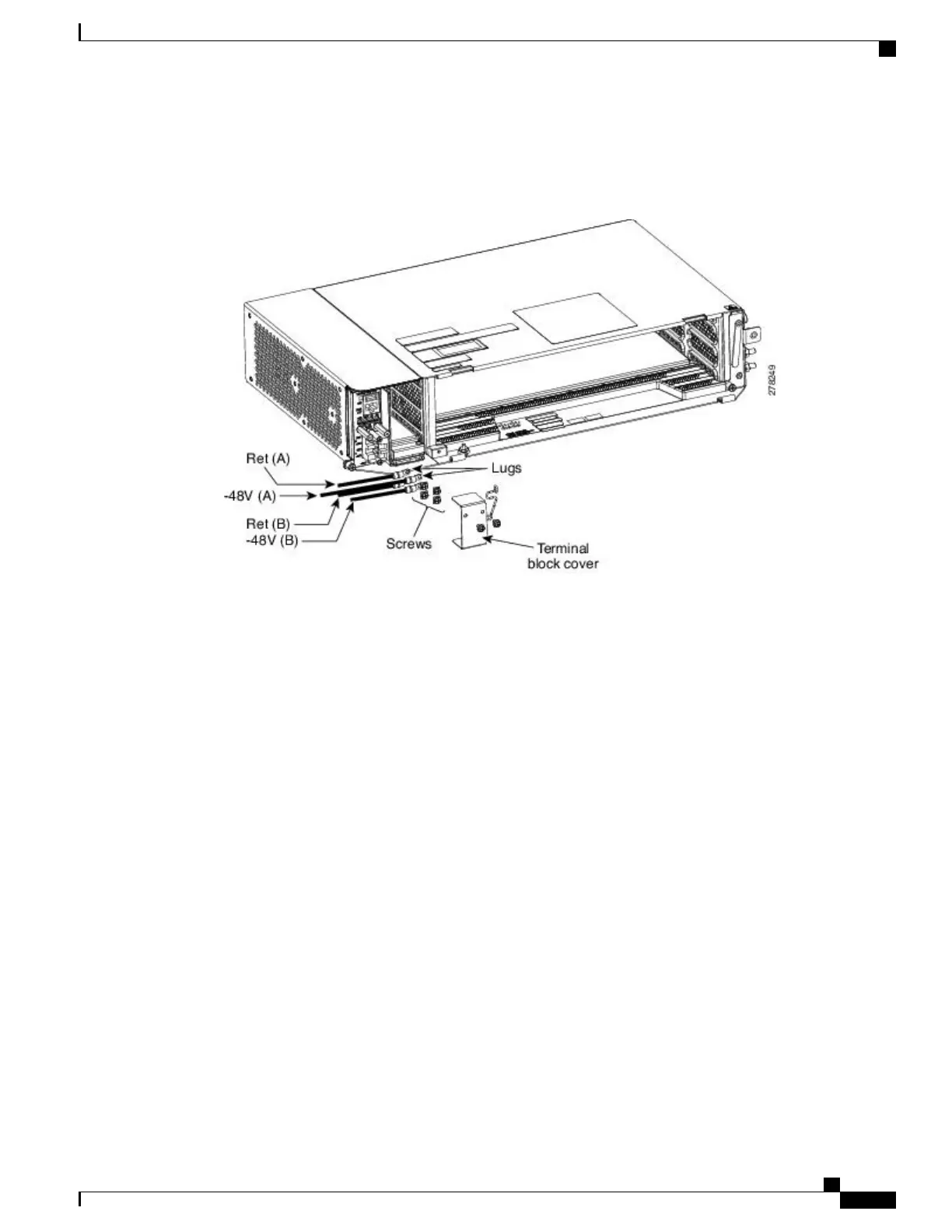
Insert the lugs as shown in the figure below.
Figure 47: Connecting Office Power
—
DC Power Module (ANSI Only)
There are two DC power terminals—A and B. Each power terminal is connected with two cables—one
for RET and the other for -48V.
Note
Step 10
Tighten the screws to a torque value of 7 in-lb (0.79 N-m) to lock the lugs.
Step 11
Tighten the screws to a torque value of 4 in-lb (0.45 N-m) of the terminal block protective cover on the DC
power module (see the figure below).
Cisco NCS 2000 Series Hardware Installation Guide
87
Connecting Power and Ground
DLP-L50 Connecting Office Power (DC) to the NCS 2002 Shelf (ANSI Only)