Step 3
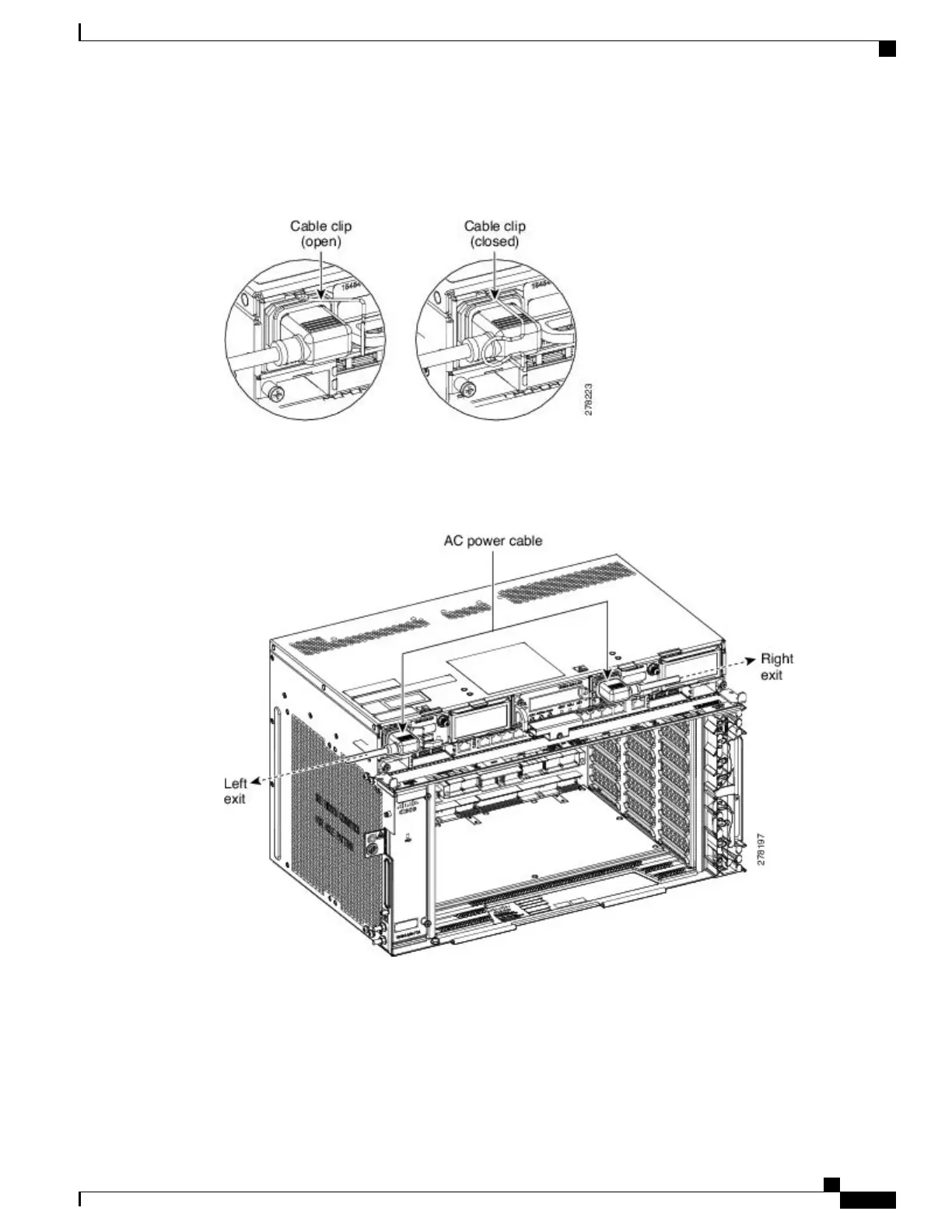
Close the cable clip to secure the power cable (see the figure below).
Figure 120: Cable Clip to Secure the Power Cable
For Slot A power module, the power cable exits from the left side. For Slot B power module, the
power cable exits from the right side (see the figure below).
Note
Figure 121: Power Cable Exit
Step 4
Connect the power cable to the fuse panel or power source.
The voltage rating value for AC power ranges between 100 VAC to 240 VAC depending on the
standards in various countries.
Note
Turn on the power after installing the power
cables.
Note
Step 5
Return to your originating procedure (NTP).
Cisco NCS 2000 Series Hardware Installation Guide
207
Connecting Power and Ground
DLP-L18 Connecting Office Power (AC) to the NCS 2006 Shelf