Step 9
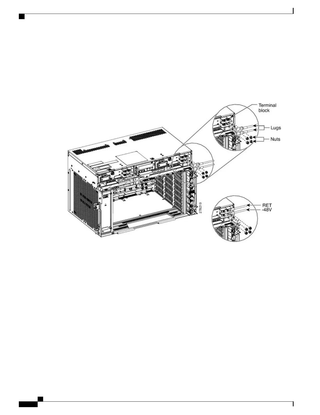
Unscrew the nuts from the terminal block (see the figure below).
Step 10
Insert the lugs as shown in the figure below. The top cable is for RET and the bottom cable is for –48 V/–60
V.
Step 11
Insert the lock washers and nuts to the terminal block (see the figure below). Tighten the nuts to a torque value
of 20 in-lb (2.25 N-m).
Figure 123: Connecting Office Power
—
DC Power Modules (ANSI Only)
Step 12
Mount the terminal block protective covers on the DC power modules (see the figure below).
For Slot A power module, the power cable exits from the left side. For Slot B power module, the
power cable exits from the right side
Note
Cisco NCS 2000 Series Hardware Installation Guide
212
Connecting Power and Ground
DLP-L19 Connecting Office Power (DC) to the NCS 2006 Shelf ( Only)