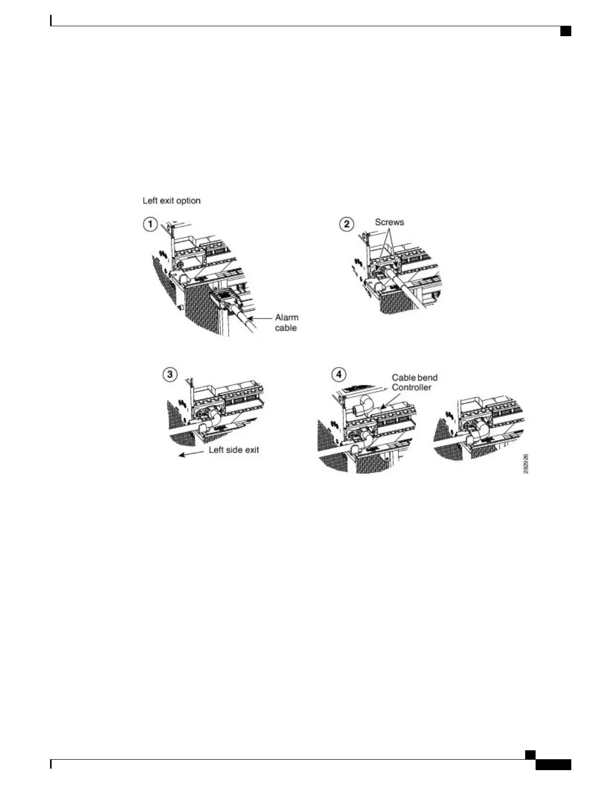
Step 2
Tighten the screws of the SCSI connector to a torque value of 4 in-lb (0.45 N-m) using #2 Philips Dynamometric
screwdriver. See Diagram 2 of the figures below.
Step 3
Bend the cable at an angle of 90° to exit from the left side or the right side (see the figures below ).
Step 4
Snap the cable bend controller on the cable. See Diagram 4 of the figures below.
Step 5
Return to your originating procedure (NTP).
Figure 134: Installing the ECU Alarm Cable
—
Left Exit Option
Figure 135: Installing the ECU Alarm Cable
—
Right Exit Option
Cisco NCS 2000 Series Hardware Installation Guide
231
Connecting and Routing the Cables
DLP-L26 Installing Alarm Wires in NCS 2006