Table 13: SCSI Alarm Cable (15454-M-ALMCBL) and SCSI Alarm Patch Cable (15454-M-AEXPCBL) Connector Details
Input-Output Alarms - Left
Connector
Input Alarms - Right
Alarm Connector
Color CodePin Number
Minor Audible Alarm +Input Pair #1 +Black/Brown1
Major Audible Alarm +Input Pair #2 +Black/Red2
Critical Audible Alarm +Input Pair #3 +Black/Orange3
Remote Audible Alarm +Input Pair #4 +Black/Yellow4
Minor Visual Alarm +Input Pair #5 +Black/Green5
Major Visual Alarm +Input Pair #6 +Black/Blue6
Critical Visual Alarm +Input Pair #7 +White/Blue7
Remote Visual Alarm +Input Pair #8 +White/Orange8
—
Input Pair #9 +White/Green9
Alarm Cutoff (ACO) +Input Pair #10 +White/Brown10
Cisco NCS 2000 Series Hardware Installation Guide
232
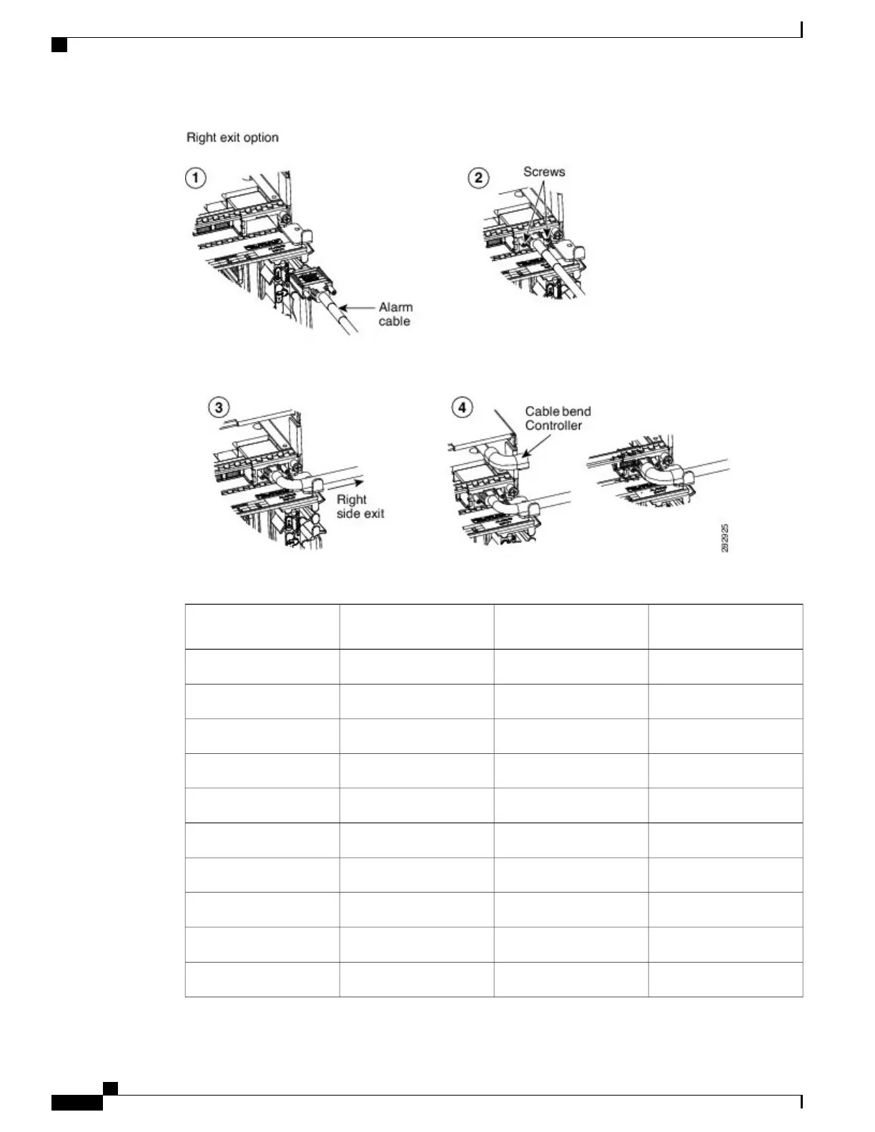
Connecting and Routing the Cables
DLP-L26 Installing Alarm Wires in NCS 2006