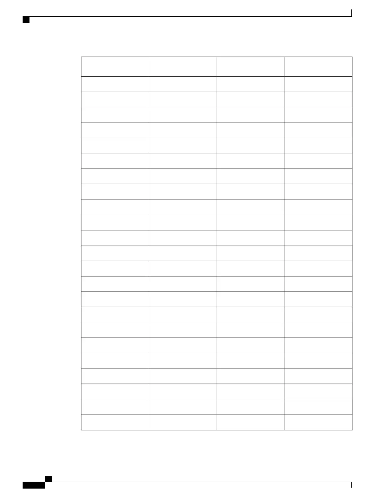
Input-Output Alarms - Left
Connector
Input Alarms - Right
Alarm Connector
Color CodePin Number
Remote Audible Alarm +Input Pair #4 +Black/Yellow4
Minor Visual Alarm +Input Pair #5 +Black/Green5
Major Visual Alarm +Input Pair #6 +Black/Blue6
——
White/Blue7
Remote Visual Alarm +Input Pair #8 +White/Orange8
—
Input Pair #9 +White/Green9
Alarm Cutoff (ACO) +Input Pair #10 +White/Brown10
———
11
———
12
———
13
Minor Audible Alarm -Input Pair #1 -Brown/Black14
Major Audible Alarm -Input Pair #2 -Red/Black15
———
16
Remote Audible Alarm -Input Pair #4 -Yellow/Black17
Minor Visual Alarm -Input Pair #5 -Green/Black18
Major Visual Alarm -Input Pair #6 -Blue/Black19
———
20
Remote Visual Alarm -Input Pair #8 -Orange/White21
—
Input Pair #9 -Green/White22
Alarm Cutoff (ACO) -Input Pair #10 -Brown/White23
———
24
———
25
———
26
Cisco NCS 2000 Series Hardware Installation Guide
234
Connecting and Routing the Cables
DLP-L26 Installing Alarm Wires in NCS 2006