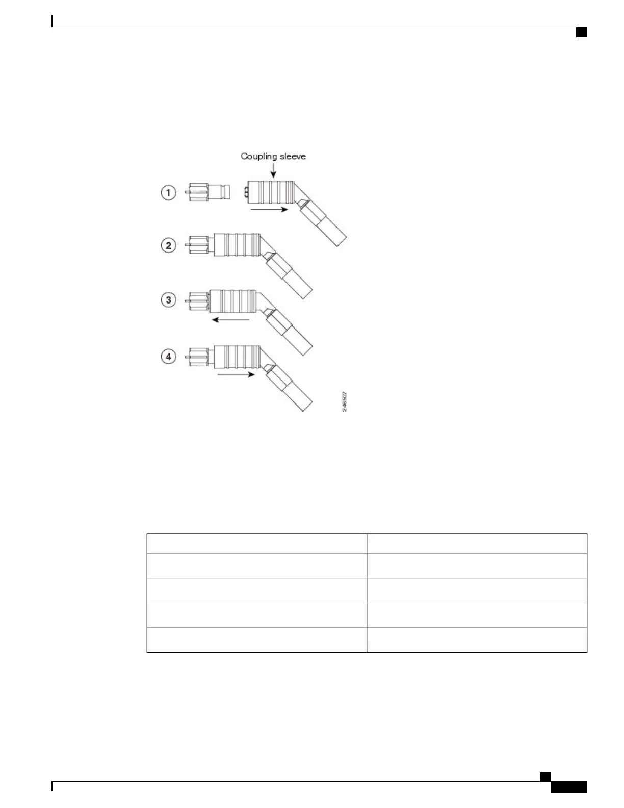
To unlock the cable connector from the ECU module connector, hold the connector and slide the
coupling sleeve backward. See diagram 4 of the figure below.
Note
Figure 139: Sequence to Attach the Connectors
The ECU modules provides 1.0/2.3 miniature coaxial connectors used for timing input and output.
The top connectors are for “A” (BITS-1) timing, and the bottom connectors are for “B” (BITS-2)
timing. In each case, the left connector is the input and the right connector is the output. The input
connectors for timing provide a 75-ohm termination.
Note
Step 3
Connect the other end of the cable to the external source of the timing signal according to the table below .
Repeat for each cable.
Table 16: ECU module Pin Assignments - ETSI
FunctionPin
Input from external driveIN 1
Output to external driveOUT 1
Input from external driveIN 2
Output to external driveOUT 2
Cisco NCS 2000 Series Hardware Installation Guide
239
Connecting and Routing the Cables
DLP-L28 Installing Timing Wires in NCS 2006 - ETSI