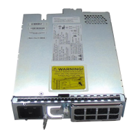
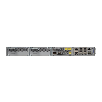
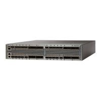
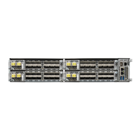
The front door of the NCS 2015 shelf allows access to the shelf, fan-tray assembly, fiber-routing area, power
connectors, external alarms and controls, timing input and output, and craft interface terminals. The front door
also acts as a protective panel. The fiber or cable guide used in the NCS 2015 shelf provides improved fiber
management.
The air in the NCS 2015 chassis is drawn in through a two-inch inlet at the bottom of the chassis, and expelled
at the top-rear as seen in the following figure.
Figure 5: Airflow Direction in the NCS 2015 DC Chassis
The NCS 2015 is mounted on a 19-inch or 23-inch ANSI rack (482.6 or 584.2 mm), or on a 600 x 300-mm
(23.6 x 11.8-inch) ETSI standard equipment rack. The rack is mounted using mounting brackets.
When installed in an equipment rack, the Cisco NCS 2015 shelf is typically connected to a fuse and alarm
panel to provide centralized alarm connection points and distributed power for the NCS 2015. Fuse and alarm
Cisco NCS 2000 Series Hardware Installation Guide
7
Overview
Cisco NCS 2015 Shelf
 Loading...


