Screw4Fan tray3
Fan tray guide and lock
plate
5
Step 4
Push the fan-tray assembly such that the backplane connector is engaged completely.
Step 5
Tighten the captive screws to a torque value of 4 in-lb (0.45 N-m) to lock the fan-tray assembly into the chassis
(see the figure below).
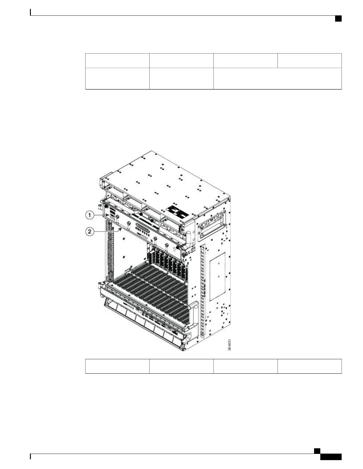
Figure 227: Fan Tray Assembly Installed in NCS 2015 DC Shelf
Fan tray handle2Fan tray1
Step 6
To verify that the tray has plugged into the assembly, check the fan tray and listen to determine if the fans are
running. When the power line is connected, a green LED indicates that the fan-tray assembly is functioning.
If power has not yet been turned on, verify that the fan tray is seated and secured with the captive screws.
Stop. You have completed this procedure.
Cisco NCS 2000 Series Hardware Installation Guide
397
Installing the Cisco NCS 2015 Door and Other Modules
NTP-L54 Installing Fan-Tray Assembly in NCS 2015 Shelf