NOTE: Due to the proximity of the encoder strip to the greased sliding rod, it is easy to dirty the strip with
grease when performing any repair operation in the area. Please clean any grease from the encoder strip if
necessary. A dry cloth can be used for this purpose, to prevent any deformation or strain on the encoder strip
while performing the cleaning.
Printer electronics, power supply, and cables
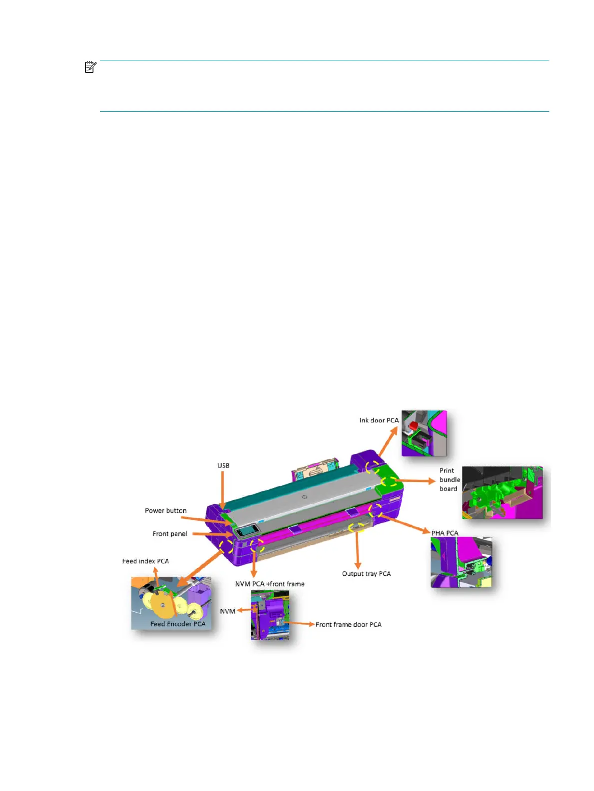
The printer contains several electronics boards and electrical and electronic components in dierent
locations.
●
There are three main active boards (Main PCA, Printer Bundle Board, and MFP only; Scanner Bundle
Board).
●
One WiFi Module, which provides the WiFi functionality to the printer.
●
One interface board (Carriage PCA), which provides and converts the appropriate signals for the Carriage
(printhead interface and line sensor signaling) .
●
Five on/o sensor PCAs (Central Window[SFP]/Front Window[MFP], Out of Paper Sensor, Output Tray
Sensor, Ink Door sensor and PHA Door sensor).
●
One NVM Back up memory PCA for storing all factory calibration values.
●
One encoder sensor and a feed index sensor (other than the encoder sensors located inside the
Rewinder, the Right Gear Module, and the Service Station).
●
One Power Button PCA. Located in the front panel, it is used to power the printer on and o.
●
One Power Supply (PSU), which converts the AC power line (110–240 V AC) into the DC power needed by
the printer (32 V and 12 V).
The standard wiring used in the printer is Flat Flexible Cables (FFCs), to interconnect all boards (including
sensors and encoders) and distributed cables for power signals to the motors.
ENWW Subsystems 41
 Loading...

