160 Keysight M8000 Series of BER Test Solutions User Guide
4 User Interface - M8020A Display Views
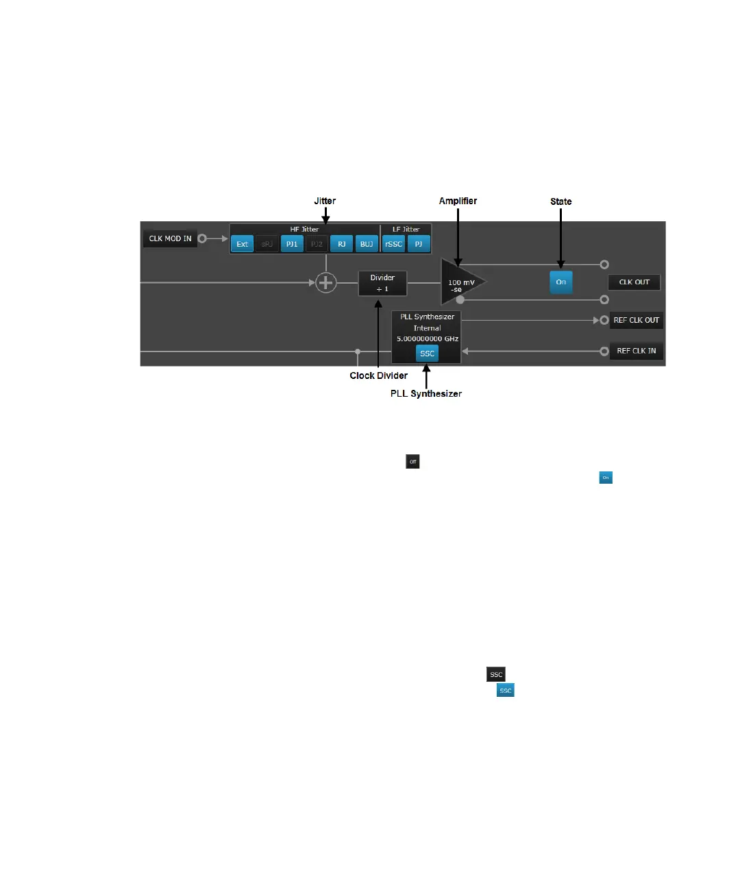
Clock
The following section of the System View represents the clock function:
The clock function allows you to apply settings on the Clock Out port or
location. It includes the following blocks:
• State - Click on the button to enable the output of Clock Source.
Once the output is enabled, the button changes to “ON” . If you
press the button again, it will turn the state “OFF”.
• Jitter - Use this block to enable the elements of High Frequency Jitter,
Low Frequency. For more details on jitter, refer to Jitter Setup on
page 296.
• Amplifier - Use this block to set the parameters related to amplifier of
the clock output.
• Clock Divider - Use this block to set a factor on which the output signal
will be divided.
• PLL Synthesizer - This block represents the currently selected clock
source. You can change the clock source by clicking on this block and
the modify the respective parameter in Parameters pane. To enable the
SSC state jitter source, click on the button. Once the SSC state is
enabled, the button changes to “ON” . This is how the bit rate is
set. For example, 5 GHz sets the bit rate to 5 Gb/s. If you press the
button again, it will turn the state “OFF”.

 Loading...


