RTC6 boards
Doc. Rev. 1.0.21 en-US
16 Appendix A: The RTC6 Ethernet Board
883
12-Bit Analog Output Ports
As with RTC6 PCIe Boards, see Chapter 4.6.1
”LASER Connector”, page 73. However, note that the
pin numbers differ.
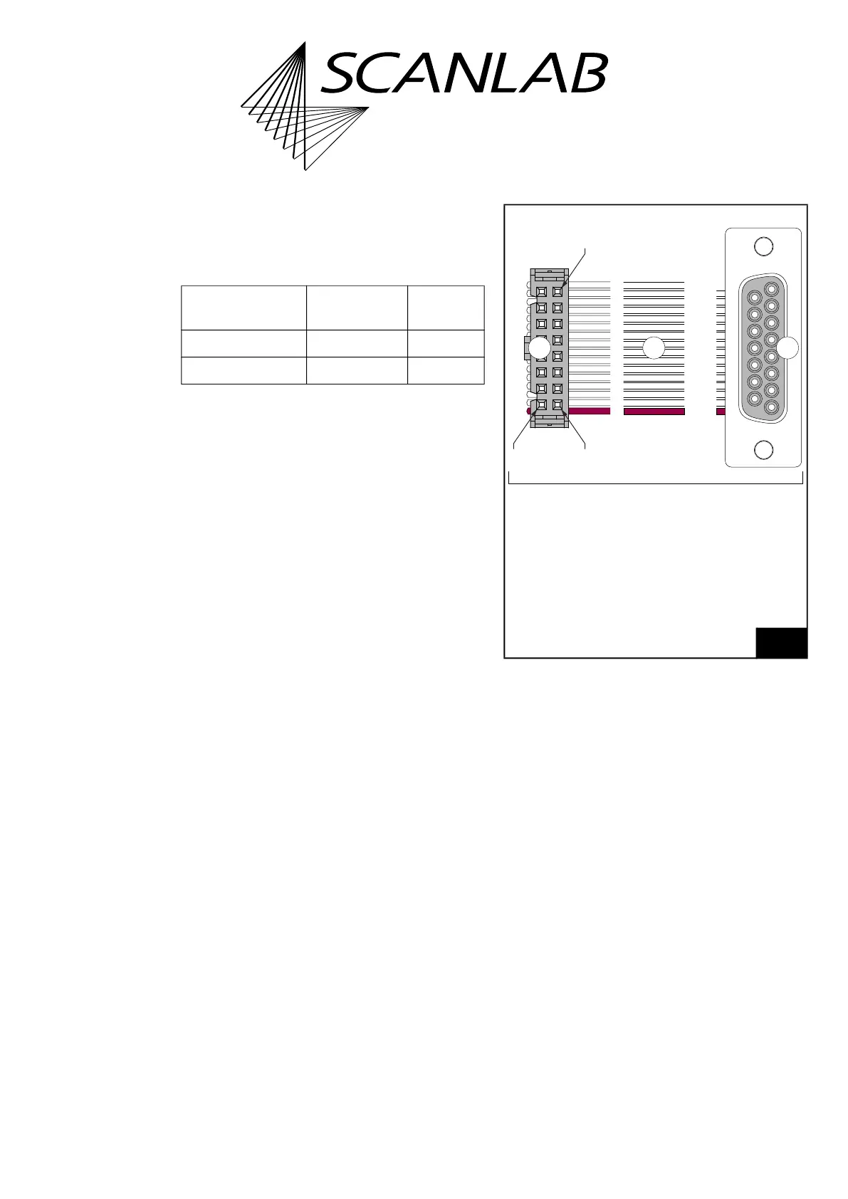
Input and Output Wiring
The input and output wiring of the 16-pin LASER
socket connector is shown in Figure 77. It is identical
to RTC6 PCIe Boards, except the pin numbers.
Signal RTC6 Ethernet
Board
RTC6 PCIe
Board
ANALOG OUT1 Pin (15) Pin (08)
ANALOG OUT2
(a)
(a) With the RTC6 PCIe Board the ANALOG OUT2 signal is
additionally available at the MARKING ON THE FLY
socket connector.
Pin (14) Pin (15)
76
Cable (proposal). Actual implementation may differ
according to customer needs.
The depicted items are not in the standard scope of delivery
of the RTC6 Ethernet Board!
1
9
8
15
321
01->01
02->09
03->02
04->10
05->03
06->11
07->04
08->12
09->05
10->13
11->06
12->14
13->07
14->15
15->08
16-> x
01
02
03
04
05
06
07
08
09
10
11
12
13
14
15
16
Pin 2Pin 1
Pin 16
Corresponds functionally to cable #116048 (l=0.2 m).
Wire
Legend
1. Connector, 16-pin female. For LASER
socket connector, see Figure 75.
Identical in construction to Würth 61201623021.
2. Flat ribbon cable 26 AWG, 20 conductors,
pitch 1.27 mm.
3. Connector, 15-pin D-SUB, female.