RTC6 boards
Doc. Rev. 1.0.21 en-US
16 Appendix A: The RTC6 Ethernet Board
882
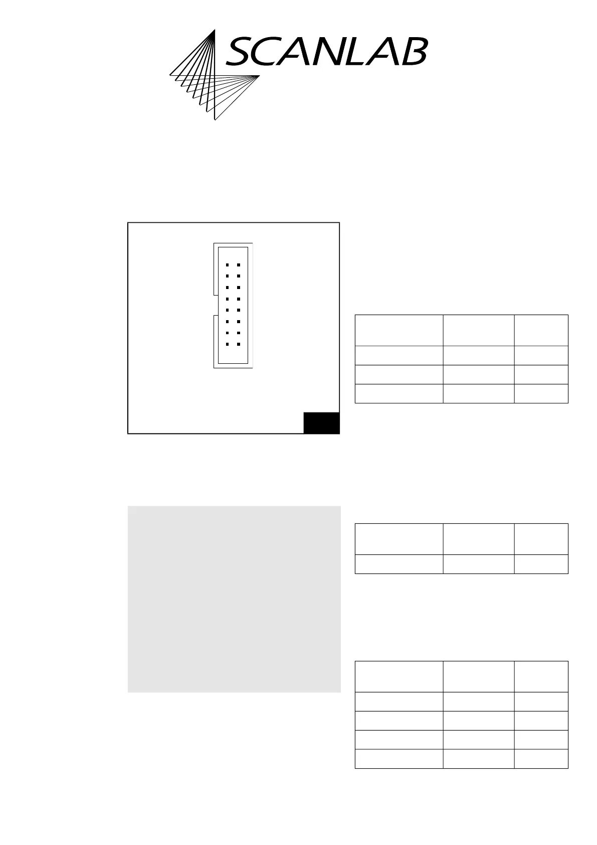
16.2.4 LASER Socket Connector
The LASER socket connector has 16 pins
(1)
. It is
located on the upper side of the RTC6 Ethernet
Board, see Figure 72, number 1.
The pin-out is shown in Figure 75.
Notes
• With RTC6 Ethernet Boards, GND is the ground at
the POWER connector. See Chapter 16.2.6
”POWER Socket Connector”, page 887. With the
RTC6 PCIe Board, GND is the PC ground.
• A suitable 0.2 m cable (#116048) is available
from SCANLAB, see also Figure 76.
Laser Control Signals
As with RTC6 PCIe Boards, see Chapter 4.6.1
”LASER Connector”, page 73. However, note that the
pin numbers differ.
External Control Signals
As with RTC6 PCIe Boards, see Chapter 4.6.1
”LASER Connector”, page 73.
BUSY List Execution Status
As with RTC6 PCIe Boards, see Chapter 4.6.1
”LASER Connector”, page 73. However, note that the
pin numbers differ.
2-Bit Digital Input Port and 2-Bit Digital
Output Port
As with RTC6 PCIe Boards, see Chapter 4.6.1
”LASER Connector”, page 73. However, note that the
pin numbers differ.
(1) With RTC6 PCIe Boards: 15 pin D-SUB connector,
female.
75
LASER socket connector: pin-out. The pitch of the pins is
2.54 mm. On RTC6 Ethernet Boards without Option
“DC/DC Converter”, GND and GND2 are identical. On
RTC6 Ethernet Boards with Option “DC/DC Converter”,
GND2 and the laser output signal are galvanically
decoupled from GND.
Notice!
• If you want to use the RTC6 Ethernet Board in
conjunction with laserDESK, observe the
following:
– laserDESK uses additional pins on the
EXTENSION 1 Socket Connector, for example,
to control the laser.
– Refer to the extended documentation for the
LASER connector which can be found in the
laserDESK online help
(alternatively available from SCANLAB or in
laserDESK-zip, which can be downloaded
from the SCANLAB website).
BUSY OUT (07) (08) DIGITAL OUT1
DIGITAL OUT2 (09) (10) DIGITAL IN1
DIGITAL IN2 (11) (12) GND
+5 V (13) (14) ANALOG OUT2
LASER1 (01) (02) LASER2
LASERON (03) (04) GND2
/START (05) (06) /STOP
ANALOG OUT1 (15) (16) NOT CONNECTED
Identical in construction to Würth 61201620621.
Signal RTC6 Ethernet
Board
RTC6 PCIe
Board
LASERON Pin (03) Pin (02)
LASER1 Pin (01) Pin (01)
LASER2 Pin (02) Pin (09)
Signal RTC6 Ethernet
Board
RTC6 PCIe
Board
BUSY OUT Pin (07) Pin (04)
Signal RTC6 Ethernet
Board
RTC6 PCIe
Board
DIGITAL IN1 Pin (10) Pin (13)
DIGITAL IN2 Pin (11) Pin (06)
DIGITAL OUT1 Pin (08) Pin (12)
DIGITAL OUT2 Pin (09) Pin (05)