RTC6 boards
Doc. Rev. 1.0.21 en-US
16 Appendix A: The RTC6 Ethernet Board
879
16.2 Layout, Interfaces, Jumper Settings
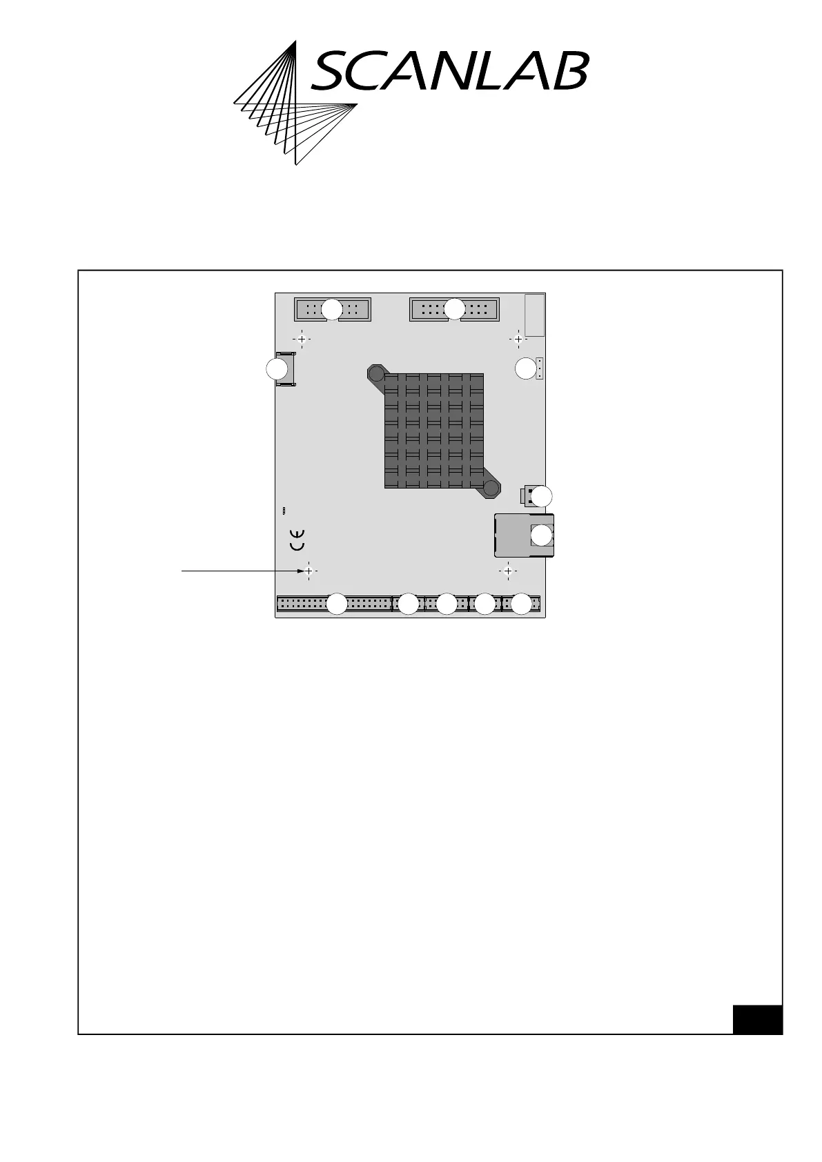
16.2.1 Layout – Upper Side
72
RTC6 Ethernet Board V1.2. Upper side.
SPI/ANA/UARTSTEPPERMOFEXT.2EXTENSION 1
SCANHEADsLASER
POWER
GND
ETH
Master
Force
DHCP
3
J0501
1
1
SN
11
10
9
8
7 6 5
4
3
2
1
Mounting hole
4x
Legend
1. LASER . . . . . . . . . . . . . . . . 16-pin socket connector. To connect the laser. With digital and analog outputs.
For details, see “LASER Socket Connector”, page 882.
2. SCANHEADs. . . . . . . . . . . . 20-pin socket connector. To connect the first and second scan head.
For details, see “SCANHEADs Socket Connector”, page 885.
3. POWER . . . . . . . . . . . . . . . 2-pin socket connector. For the voltage supply.
For details, see “POWER Socket Connector”, page 887.
4. ETH . . . . . . . . . . . . . . . . . . RJ-48 8P8C connector. For the network connection.
For details, see Chapter 16.2.7 ”ETH Connector”, page 887.
5. SPI/ANA/UART . . . . . . . . . . 12-pin socket connector. Hardware interface for several data exchange methods.
With analog input ports. For details, see “SPI/ANA/UART Socket Connector”, page 888.
6. STEPPER. . . . . . . . . . . . . . . 10-pin socket connector. For controlling up to two stepper motors.
For details, see “STEPPER Socket Connector”, page 889.
7. MOF . . . . . . . . . . . . . . . . . 14-pin socket connector. Hardware interface for encoder pulses, for example, for Processing-on-the-fly
applications. For details, see “MARKING ON THE FLY Socket Connector”, page 82.
8. EXT. 2 . . . . . . . . . . . . . . . . 10-pin socket connector. With a 8-bit digital output port.
For details, see “EXTENSION 2 Socket Connector”, page 80.
9. EXTENSION 1. . . . . . . . . . . 40-pin socket connector. With a 16-Bit Digital Output and
a 16-Bit digital input port. For details, see “EXTENSION 1 Socket Connector”, page 78.
10. Master. . . . . . . . . . . . . . . . 6-pin socket connector. To connect with another RTC6 board for the purpose of synchronize clocks. For
details, see “Master Socket Connector, Slave Socket Connector”, page 893.
11. Force DHCP . . . . . . . . . . . . Jumper field Jumper field to ignore or not to ignore the saved static IP address.
For details, see “Jumper Field ’Force DHCP’”, page 897.