RTC6 boards
Doc. Rev. 1.0.21 en-US
16 Appendix A: The RTC6 Ethernet Board
893
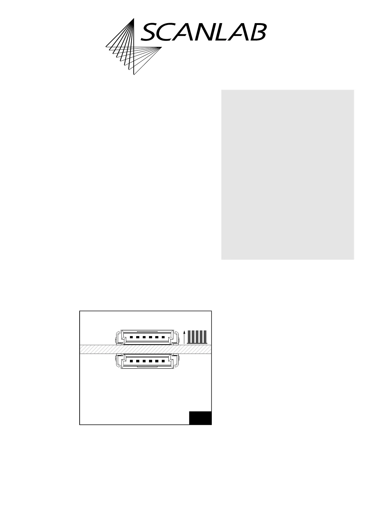
16.2.13Master Socket Connector,
Slave Socket Connector
The Master socket connector has 6 pins, see
Figure 87. It is located on the upper side of the
RTC6 Ethernet Board, see Figure 72, number 10.
The Slave socket connector has 6 pins, see Figure 87.
It is located on the lower side of the RTC6 Ethernet
Board, see Figure 72, number 16.
The both socket connectors serve to synchronize the
clock cycles of several RTC6 boards.
Connection cables are available from SCANLAB, see
Figure 9, page 66. The necessary information for
assembling your own cables is shown in Figure 8,
page 66.
For further information, see
• Chapter 6.6.3 ”Master/Slave Operation”,
page 124
• Chapter 9.3.1 ”Starting and Stopping Lists by
External Control Signals and Master/Slave
Synchronization”, page 289.
A specific hardware revision of the RTC6 Ethernet
Board is required for proper functioning of the
master/slave clock synchronization (see label with
part number and modification index). If you have an
older RTC6 Ethernet Board or are unsure, contact
SCANLAB.
87
Master socket connector and Slave socket connector.
The pitch of the pins is 1.27 mm.
61
16
Slave
Manufacurer: ERNI.
Artikle number: 214013 (2×).
Master
(on upper side of board = side with cooling element)
(on lower side of board)
Notice!
• Master/Slave-connected RTC6 Ethernet Boards
are destroyed by different potentials. This may
even be the case, if the boards are connected to
the same power supply but the cabling is
unfavourable. Refer to Figure 88 for the
recommended wiring.
To avoid different potentials:
(1) Make sure that the power supply is switched
off.
(2) First connect one RTC6 Ethernet Board to
the power supply, and then connect the
other one through a branch of this cable
(keep the length as short as possible).
(5) Only then switch the power supply back on
again.
• Always switch off the power supply of all
Master/Slave-connected RTC6 Ethernet Boards
before disconnecting the cabling from them.