RTC6 boards
Doc. Rev. 1.0.21 en-US
16 Appendix A: The RTC6 Ethernet Board
898
16.3 Installation and Operation
16.3.1 Hardware Installation
Proceed as follows to install the RTC6 Ethernet Board
in a shielded housing:
(1) Remove the RTC6 Ethernet Board from its anti-
static bag. Do not touch the electrical contacts of
the board.
(2) Mount the RTC6 Ethernet Board at the intended
location in your shielded housing.
(3) Connect the RTC6 Ethernet Board to:
– your power supply using a power cable
– Also observe Figure 88 –
– your Ethernet port using an Ethernet cable
(4) Connect the RTC6 Ethernet Board using
appropriate cables to:
– the scan head
– the laser
(5) If you want to use the signals at the
RTC6 Ethernet Board socket connectors, then
attach appropriate cables.
Notice!
• Store the board in an electrostatically neutral
environment using the supplied anti-static bag.
• Observe ESD precautions when installing the
board.
• Do not touch the electrical contacts of the
board.
• Protect the board from moisture, dust, corrosive
vapors and mechanical loads.
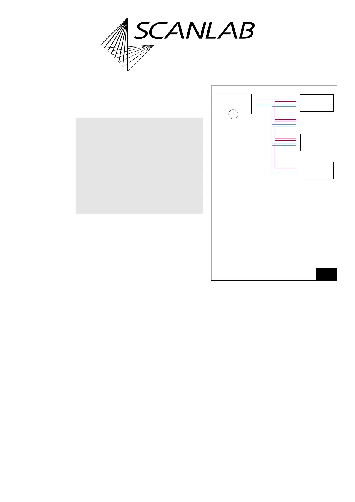
88
Recommended cabling for connecting several
RTC6 Ethernet Boards/RTC6 EtherBoxes.
Legend
1. For RTC6 Ethernet Board +11 V…+50 V
For RTC6 EtherBox +12 V…+30 V
Notice!
• For voltage supply:
– Use “daisy chain” topology
– Do not use star topology
• Applies regardless of whether the devices are
master/slave connected or not.
–
–
–
–
–
+
+
+
+
+
1
#n
RTC6 Ethernet
RTC6 EtherBox
#3
RTC6 Ethernet
RTC6 EtherBox
#2
RTC6 Ethernet
RTC6 EtherBox
#1
RTC6 Ethernet
RTC6 EtherBox
Voltage
supply