RTC6 boards
Doc. Rev. 1.0.21 en-US
16 Appendix A: The RTC6 Ethernet Board
894
16.2.14Jumper Settings
SCANLAB ships RTC6 Ethernet Boards in various
jumper configurations. The jumpers can be
reconfigured at a later time. See Chapter 2.7 ”Jumper
Settings and Type Designations”, page 40.
Solder Jumper Field A – Configuring Output
Signal Level at EXTENSION 1 Socket
Connector
• Position on the board: lower side, see Figure 73,
number 12.
• Purpose: to configure the level (5 V or 3.3 V) of all
output signals at the EXTENSION 1
socket connector, see the following table.
• See also Section ”Configuring the Output Signal
Level”, page 78.
Notice!
• Only configure allowed jumper settings.
Otherwise, the board gets damaged!
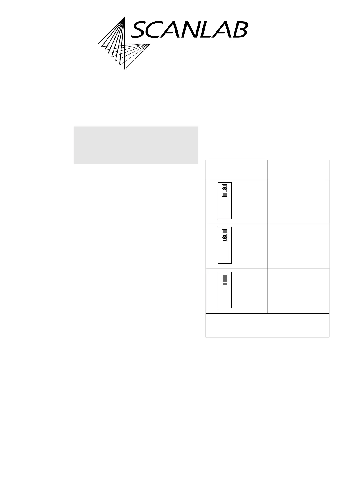
Allowed
jumper setting
At the EXTENSION 1
socket connector
Output signal level
5 V.
Output signal level
3.3 V.
No signal output.
*
Caution: make sure that only one position is closed
in this solder jumper field. Other combinations are
not allowed and cause damage to the board!
closed*
open
5V3.3V
Digital I/O Voltage
open
closed*
5V3.3V
Digital I/O Voltage
open
open
5V3.3V
Digital I/O Voltage