RTC6 boards
Doc. Rev. 1.0.21 en-US
16 Appendix A: The RTC6 Ethernet Board
895
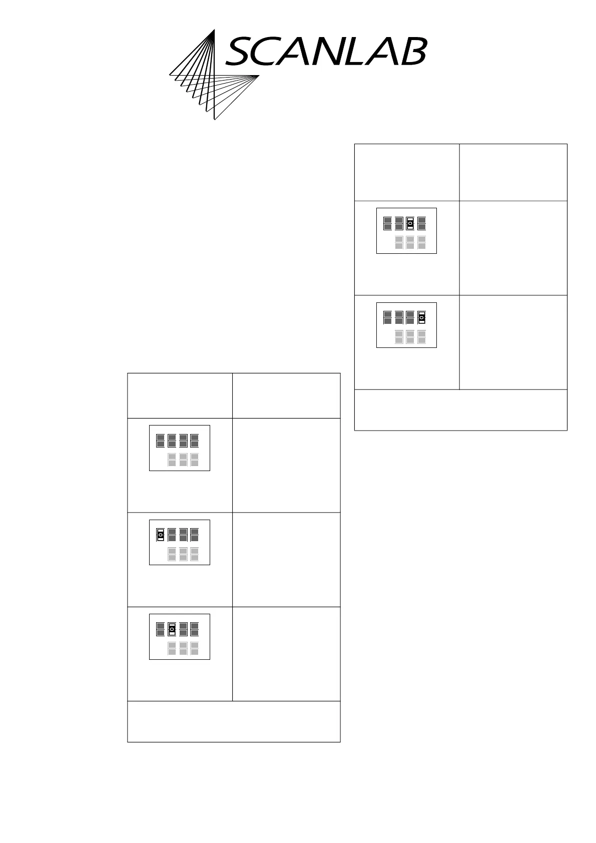
Solder Jumper Field B – Configuring pin (09)
of EXT. 2 Socket Connector
• Position on the board: lower side, see Figure 73,
number 13.
• Purpose: to configure the signal at
pin (09) of the EXT. 2 socket connector, see the
following table.
• See also “Configuration by Solder Jumpers”,
page 80.
• Configurations of solder jumper field B and
solder jumper field C are independent from each
other.
• On the RTC6 Ethernet Board the printed label of
solder jumper field B is ’Pin 17’. This has been
chosen deliberately in order to keep consistency
with already existing RTC boards. Even though
pin (09) is actually configured.
Allowed
jumper setting
Output at the EXT. 2
socket connector
pin (09)
No signal.
LATCH signal.
GROUND
(low level).
*
Caution: make sure that only one position is closed
in this solder jumper field. Other combinations are
not allowed and cause damage to the board!
open
open
open
Pin15 Pin17
Latch GND +5V Data7
open
open
open
open
closed*
Pin15 Pin17
Latch GND +5V Data7
closed*
open
open
Pin15 Pin17
Latch GND +5V Data7
open
Allowed
jumper setting
(cont’d)
Output at the EXT. 2
socket connector
pin (09)
(cont’d)
+5 V
(high level).
DATA7
(a)
.
(a) Synonym: Data Bit #7. MSB of the 8-bit output value.
*
Caution: make sure that only one position is closed
in this solder jumper field. Other combinations are
not allowed and cause damage to the board!
open
closed*
open
Pin15 Pin17
Latch GND +5V Data7
open
open
open
closed*
Pin15 Pin17
Latch GND +5V Data7
open