RTC6 boards
Doc. Rev. 1.0.21 en-US
16 Appendix A: The RTC6 Ethernet Board
892
Notes
• Required parts for the mating connector are
not included in the scope of delivery:
Manufacturer: Amphenol FCI
Series. Minitek
®
1× Housing, part number 90311-010LF
10× Contact, part number 77138-101LF.
• The pin (08) and pin (09) are configurable by
solder jumpers.
• RTC6 Ethernet Boards do not have pins for
LASER1 and LASER2 at their (10-pin) EXT. 2
socket connectors.
Configuration by Solder Jumpers
The pin (08) of the EXT. 2 socket connector is
configured by the solder jumper field C whereas
pin (09) is configured by solder jumper field B.
Both jumper fields are on the lower side of the
RTC6 Ethernet Board, see Figure 73. For further
information, see Section ”Solder Jumper Field B –
Configuring pin (09) of EXT. 2 Socket Connector”,
page 895 and Section ”Solder Jumper Field C –
Configuring pin (08) of EXT. 2 Socket Connector”,
page 896.
Notes
• If the DATA7 bit (DATA7) is assigned to pin (08),
then the full 8-bit output value is available at the
output port (pins (1) to pin (08) of the EXT. 2
socket connector).
• If pin (08) is set to +5 V (HIGH level), an offset of
128 results for the output value. That is, the
output value range is from 128…255.
• If pin (08) ist set to GND (LOW level) the output
value range is restricted to 0…127.
• The DATA7 bit can be used for other purposes by
assigning it to pin (09).
8-Bit Digital Output Port
As with RTC6 PCIe Board, see Section ”8-Bit Digital
Output Port”, page 81.
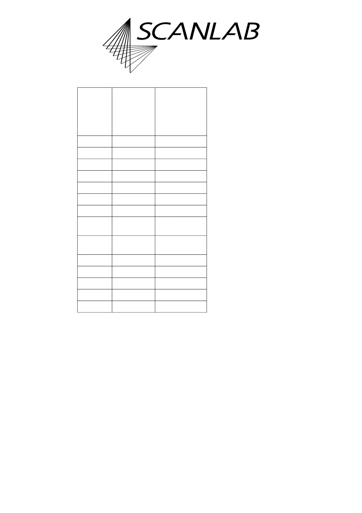
Signal RTC6 Ethernet
Boards,
EXT. 2
socket connect
or
10 pins
RTC6 PCIe Boards,
EXTENSION 2,
26 pins
DATA0 Pin (01) Pin (01)
DATA1 Pin (02) Pin (03)
DATA2 Pin (03) Pin (05)
DATA3 Pin (04) Pin (07)
DATA4 Pin (05) Pin (09)
DATA5 Pin (06) Pin (11)
DATA6 Pin (07) Pin (13)
*, see in
Figure 24
Pin (08) Pin (15)
**, see in
Figure 24
Pin (09) Pin (17)
GND Pin (10) Pin (02)
+5 V – Pin (06), (18), (25)
LASER1 – Pin (22)
LASER2 – Pin (19)
GND2 – Pin (23)