RTC6 boards
Doc. Rev. 1.0.21 en-US
16 Appendix A: The RTC6 Ethernet Board
885
16.2.5 SCANHEADs Socket Connector
The SCANHEADs socket connector has 20 pins. It is
located on the upper side of the RTC6 Ethernet
Board, see Figure 72, number 2.
The SCANHEADs socket connector provides the same
signals as the SCANHEAD and
2. SCANHEAD
socket connector of the RTC6 PCIe Board for the first
scan head connector (pin (01)…pin (10)) and the
second scan head-connector (pin (11)…pin (20)).
The pin-out is shown in Figure 78.
A cabling example is shown in Figure 79 (the shown
Y cable is available from SCANLAB with a length of
0.2 m: #116050).
Scan system control (via an XY2-100 Converter
(Accessory), if needed) is identical to that of the
RTC6 PCIe Board.
For further information, see Chapter 4.5 ”Interfaces
to Scan System”, page 67.
78
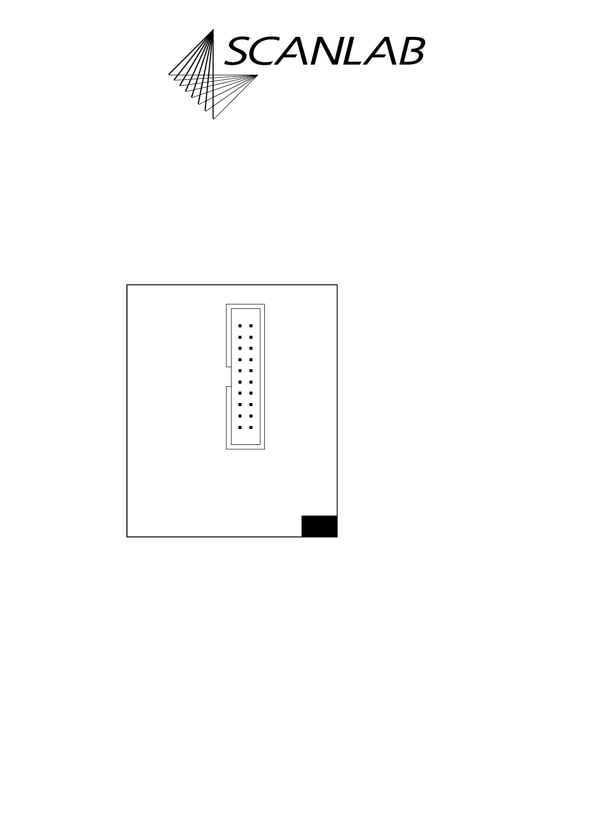
SCANHEADs socket connector: pin-out. The pitch of the
pins is 2.54 mm.
NOT CONNECTED (07) (08) DATA OUT 1–
DATA OUT 1+ (09) (10) NOT CONNECTED
DATA IN 2+* (11) (12) DATA IN 2–*
+3.3 V DO NOT CONNECT (13) (14) GND
DATA IN 1+ (01) (02) DATA IN 1–
+3.3 V DO NOT CONNECT (03) (04) GND
NOT CONNECTED (05) (06) GND
NOT CONNECTED (15) (16) GND
NOT CONNECTED (17) (18) DATA OUT 2–*
DATA OUT 2+* (19) (20) NOT CONNECTED
* Signals for the 2nd scan head: option.
Identical in construction to Würth 61202020621.