RTC6 boards
Doc. Rev. 1.0.21 en-US
16 Appendix A: The RTC6 Ethernet Board
886
79
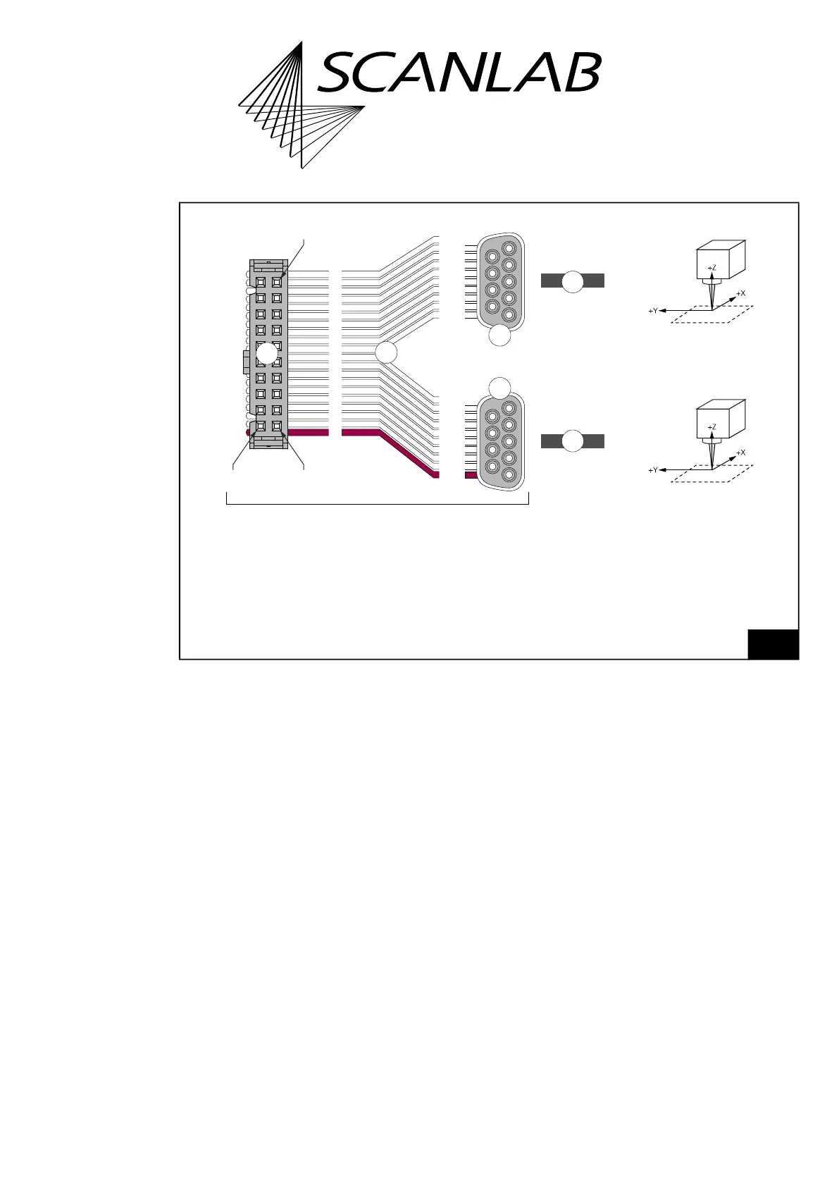
Cabling (proposal). Actual implementation may differ according to customer needs.
The depicted items are not in the standard scope of delivery of the RTC6 Ethernet Board!
4
4
3
3
2
1
10-> x
09->05
08->09
07->04
06->08
05->03
04->07
03->02
02->06
01->01
20-> x
19->05
18->09
17->04
16->08
15->03
14->07
13->02
12->06
11->01
01
02
03
04
05
06
07
08
09
10
11
12
13
14
15
16
17
18
19
20
1
2
3
4
5
6
7
8
9
1
2
3
4
5
6
7
8
9
Pin 2
Pin 20
Pin 1
Corresponds functionally to Y cable #116050 (l=0.2 m).
Scan head 1
Scan head 2
or Z axis
/ varioSCAN
Wire
Legend
1. Connector, 20-pin female. For SCANHEADs socket connector, see Figure 78.
Identical in construction to Würth 61202023021.
2. Flat ribbon cable 26 AWG, 20 conductors, pitch 1.27 mm.
3. Connector, 9-pin D-SUB, female.
4. Data cable for SL2-100 protocol. For example, #115428.