RTC6 boards
Doc. Rev. 1.0.21 en-US
16 Appendix A: The RTC6 Ethernet Board
890
Encoder Input Ports
As with RTC6 PCIe Board, see Section ”Encoder
Input Ports”, page 82.
External Control Signals
As with RTC6 PCIe Board, see Section ”External
Control Signals”, page 82.
The signals are referenced to GND, see Notes,
page 882.
BUSY OUT Status
The BUSY OUT signal at pin (13) is identical to the
BUSY OUT signal at the LASER socket connector, see
Chapter 16.2.4 ”LASER Socket Connector”,
page 882.
The signal is referenced to GND, see Notes, page 882.
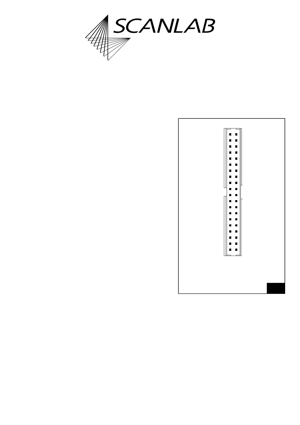
16.2.11EXTENSION 1 Socket
Connector
The EXTENSION 1 socket connector has 40 pins. It is
located on the upper side of the RTC6 Ethernet
Board, see Figure 72, number 9.
The pin-out is shown in Figure 85.
Notes
• Required parts for the mating connector are
not included in the scope of delivery:
Manufacturer: Amphenol FCI
Series. Minitek
®
1× Housing, part number 90311-040LF
40× Contact, part number 77138-101LF.
• The EXTENSION 1 socket connector on
RTC6 Ethernet Boards has a 2.00 mm pitch of the
pins, whereas RTC6 PCIe Boards have 2.54 mm.
85
EXTENSION 1 socket connector: pin-out. The pitch of the
pins is 2.00 mm.
Manufacturer: Amphenol FCI.
Product Number: 98424-F52-40LF.
DIGITAL OUT 0 (01) (02) DIGITAL IN 0
DIGITAL OUT 1 (03) (04) DIGITAL IN 1
DIGITAL OUT 2 (05) (06) DIGITAL IN 2
DIGITAL OUT 3 (07) (08) DIGITAL IN 3
DIGITAL OUT 4 (09) (10) DIGITAL IN 4
DIGITAL OUT 5 (11) (12) DIGITAL IN 5
DIGITAL OUT 6 (13) (14) DIGITAL IN 6
DIGITAL OUT 7 (15) (16) DIGITAL IN 7
DIGITAL OUT 8 (17) (18) DIGITAL IN 8
DIGITAL OUT 9 (19) (20) DIGITAL IN 9
DIGITAL OUT 10 (21) (22) DIGITAL IN 10
DIGITAL OUT 11 (23) (24) DIGITAL IN 11
DIGITAL OUT 12 (25) (26) DIGITAL IN 12
DIGITAL OUT 13 (27) (28) DIGITAL IN 13
DIGITAL OUT 14 (29) (30) DIGITAL IN 14
DIGITAL OUT 15 (31) (32) DIGITAL IN 15
LATCH OUT (33) (34) SYNC OUT
VCC OUT (35) (36) BUSY OUT
+5 V (37) (38) +5 V
GND (39) (40) GND