RTC6 boards
Doc. Rev. 1.0.21 en-US
17 Appendix B: The UFPM Extension Board
929
17 Appendix B: The UFPM Extension Board
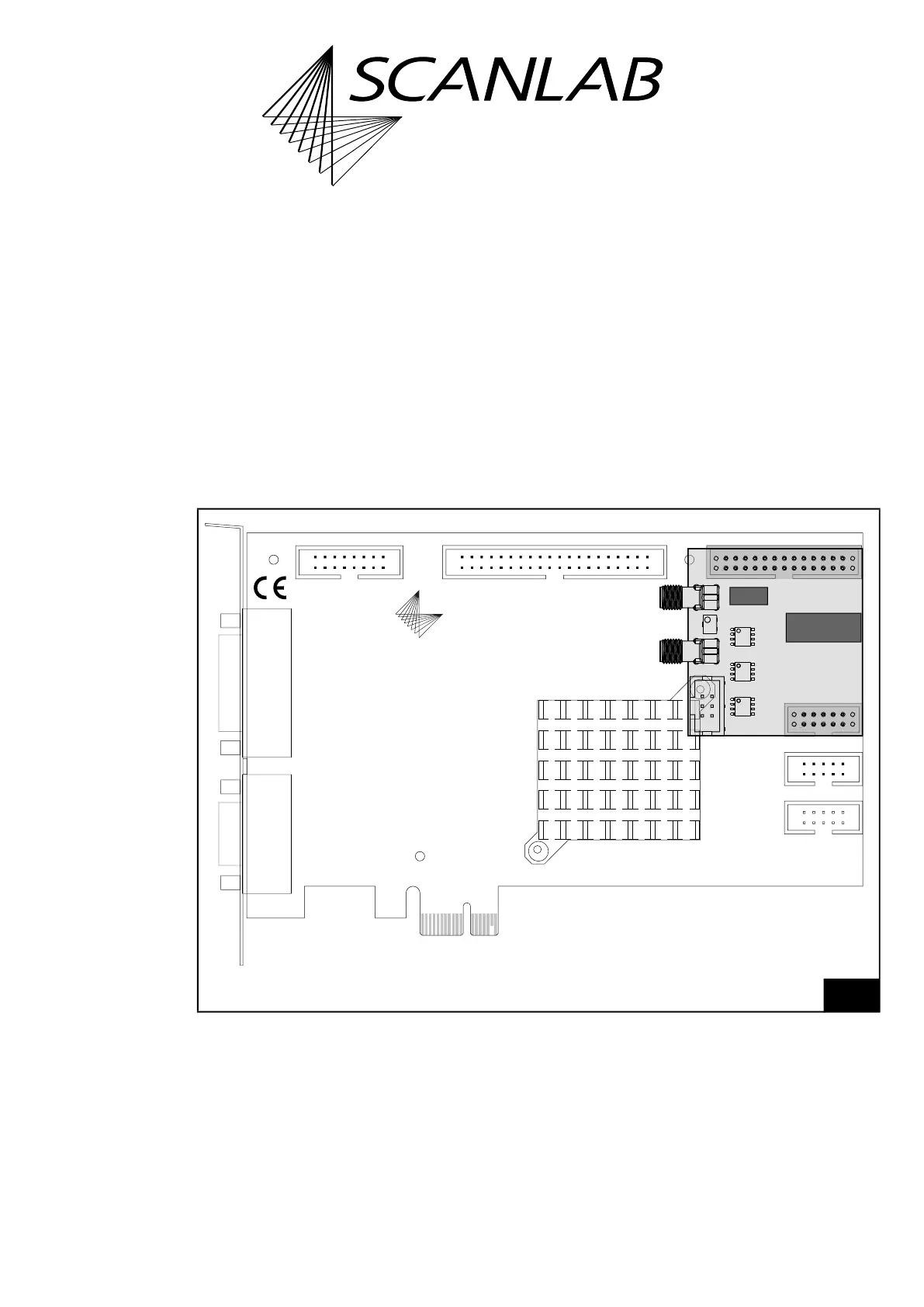
The UFPM Extension Board
(1)
has been developed for
RTC6 PCIe Boards
(2)
.
The assembly is shown in Figure 90, dimensions and
details in Figure 91.
The UFPM Extension Board converts 8-bit digital
signals into analog voltage values using a fast digital-
to-analog converter.
It is recommended, if:
• Analog controlled lasers are operated and
• Pixel output frequencies 100 kHz
(3)(4)
are to be
achieved (see set_pixel_line)
(1) For example, #137980, #140965, #152803.
(2) Cannot be uses with RTC6 Ethernet Boards for
mechanical reasons.
(3) Option “UFPM“ is mandatory for pixel output
frequencies 800 kHz…3,2 MHz.
(4) The UFPM Extension Board also supports pixel output
frequencies < 100 kHz, of course.
90
UFPM Extension Board: Assembly with the RTC6 PCIe Board.
Note: The Second Scan Head Slot Cover (Accessory) (#115132) cannot be used.
109
21
109
21
109
21
2625
21
4039
21
1615
21
LASER
SCANHEAD
SCANLAB
V1.2
RTC6
McBSP/ANALOG
RS232
STEPPER MOTOR
EXTENSION 2EXTENSION 1MARKING ON THE FLY
1