RTC6 boards
Doc. Rev. 1.0.21 en-US
17 Appendix B: The UFPM Extension Board
930
The UFPM Extension Board can be used to control the
pixel-to-pixel variation in laser power via analog
voltage values with 8 bit resolution.
Output voltage range: 0 V…5 V.
For this purpose, the outputs must be sent to
Port = 3 (8-bit digital output port at the
EXTENSION 2 socket connector), see set_pixel_line.
For all Pixel Output Modes including their extensions,
the laser pulse duration must be specified before the
beginning of the pixel line by set_laser_pulses,
set_laser_pulses_ctrl or set_laser_timing with at
least 1/64 µs duration (even if the pulse duration is
not used for laser control). Otherwise, no pulses are
outputted at LASER1.
91
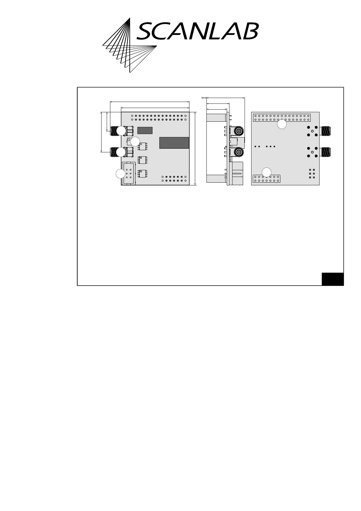
UFPM Extension Board: dimensions and details. All dimensions in mm.
2
1
4
3
2
1
5
6
*
13.6
15.2
25.4
52.8
45.4
48.7
12.3
26.3
* 3 mm (distance to the RTC6 PCB surface when mounted).
Legend
1 . . . .J1. 30-pin socket for connecting to the 26-pin EXTENSION 2 socket connector of the
RTC6 PCIe Board. The outer 4 pins of connector J1 are unconnected and only serve to prevent
misaligned insertion of the board.
2 . . . .J2. 14-pin socket for connecting to the 10-pin STEPPER MOTOR socket connector of the
RTC6 PCIe Board. Socket J2 only serves to facilitate mechanical retention to the RTC board.
3 . . . .J3. SMA connector with analog output port ANALOG OUTA.
4 . . . .J4. 6-pin socket connector with analog output port ANALOG OUTA and ANALOG OUTB.
5 . . . .J5. SMA connector with analog output port ANALOG OUTB.
6 . . . .P3. Potentiometer for fine-tuning the 5 V amplitude of analog output ports ANALOG OUTA and
ANALOG OUTB.