RTC6 boards
Doc. Rev. 1.0.21 en-US
17 Appendix B: The UFPM Extension Board
931
The UFPM Extension Board adapts the LATCH signal
duration to the pixel frequency (approx.
HalfPeriod
…5 µs). It synchronously converts the 8-bit
digital values to analog values in the range 0 V…5 V
and makes them available at its analog output ports
ANALOG OUTA and ANALOG OUTB. The connector
pin-outs on the UFPM Extension Board are shown in
Figure 92. Potentiometer P3 lets you fine-tune the
exact voltage amplitude, see Figure 91.
Software Requirements
• The UFPM Extension Board is supported by
default by the RTC6 Software Package package.
Hardware Requirements
• The pixel values are outputted as 8-bit digital
values at the 8-bit digital output of the
RTC6 PCIe Board, EXTENSION 2 socket connector.
To enable outputting of (complete) pixel values as
well as the latch signal at the EXTENSION 2
socket connector, the following solder jumper on
the RTC6 PCIe Board must be closed
(1)
:
– DATA7 in solder jumper field C
(= the DATA7 signal is outputted at pin 15 of
the EXTENSION 2 socket connector)
– LATCH in solder jumper field B
(= the LATCH signal is outputted at pin 17 of
the EXTENSION 2 socket connector)
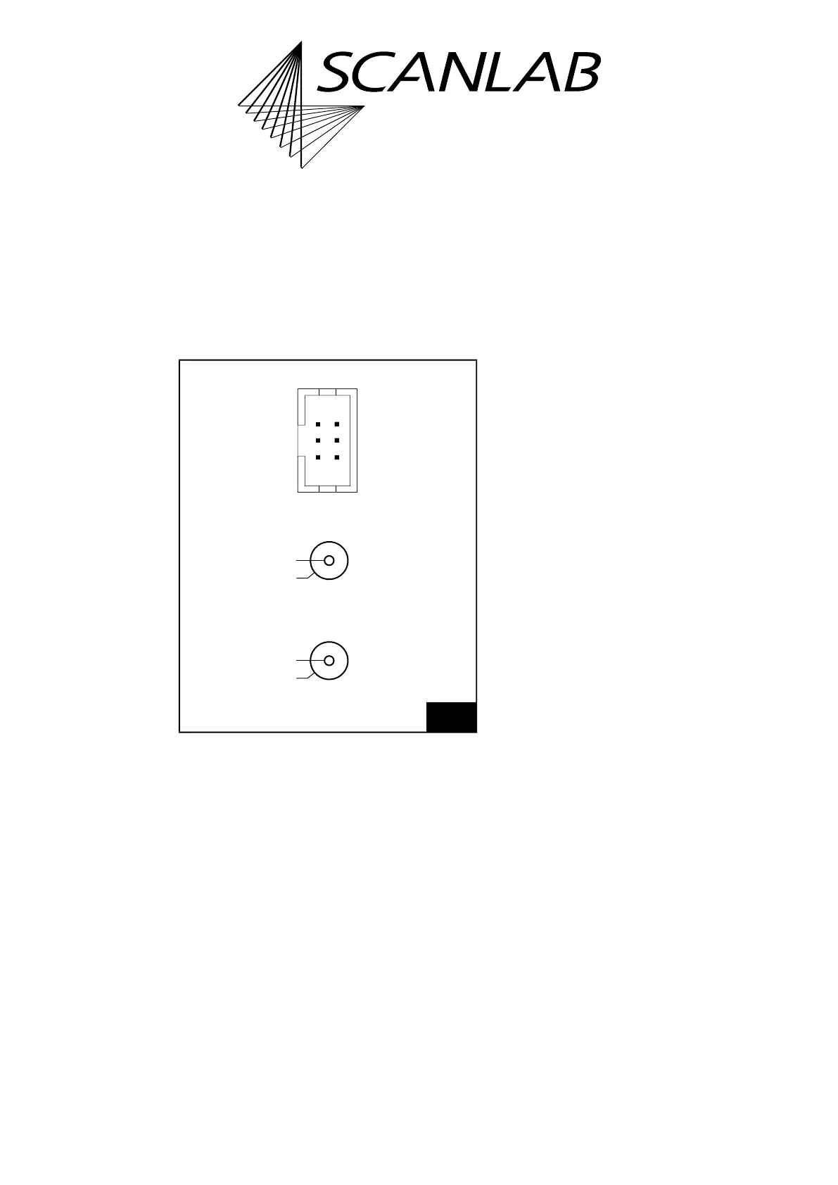
92
UFPM Extension Board: connector pin-outs.
GND (01) (02) ANALOG OUTA
GND (03) (04) ANALOG OUTB
GND (05) (06) +5 V
ANALOG OUTA (01)
GND (02)
J4 (6-pin socket connector)
J3 (SMA connector)
ANALOG OUTB (01)
GND (02)
J5 (SMA connector)
(1) Corresponds to RTC6 PCIe Boards TYPE n24.
Technical Specifications
• Dimensions
– Length 52.8 mm
– Width 48.7 mm
• Analog output ports
ANALOG OUTA, ANALOG OUTB
– Connectors 1 6-pin socket connector,
2 SMA connectors (coaxial
connectors)
– Output voltage
range
0 V…5 V
– Resolution 8 bits
– Max. current
load
5 mA
– Reference GND