Controller area network (bxCAN) RM0008
536/690
CAN filter activation register (CAN_FA1R)
Address offset: 0x21C
Reset value: 0x00
Filter bank i register x (CAN_FiRx) (i=0..13, x=1..2)
Address offsets: 0x240..0x2AC
Reset value: 0xXX where X is undefined
Note: There are 14 filter banks, i=0..13. Each filter bank i is composed of two 32-bit registers,
CAN_FiR[2:1].
This register can only be modified when the FACTx bit of the CAN_FAxR register is cleared
or when the FINIT bit of the CAN_FMR register is set.
Bits 31:14 Reserved, forced by hardware to 0.
Bits 13:0 FFAx: Filter FIFO Assignment for Filter x
The message passing through this filter will be stored in the specified FIFO.
0: Filter assigned to FIFO 0
1: Filter assigned to FIFO 1
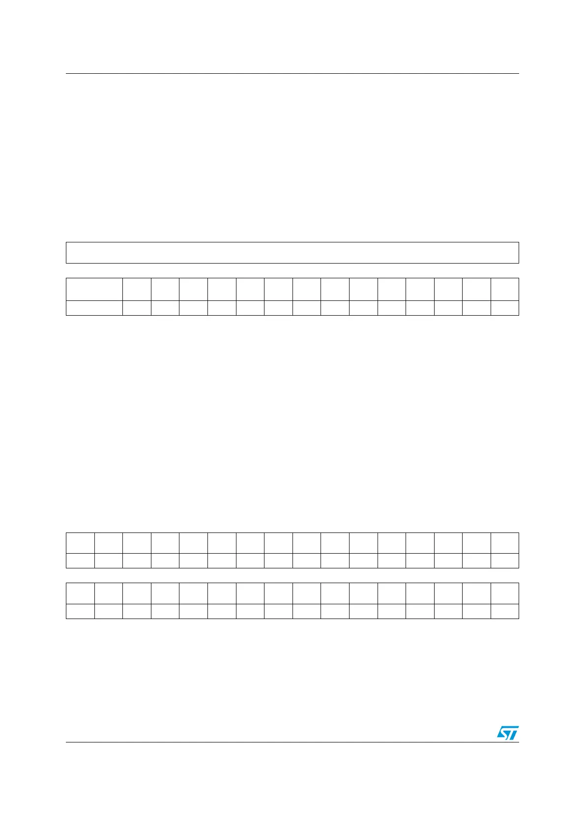
31 30 29 28 27 26 25 24 23 22 21 20 19 18 17 16
Reserved
1514131211109876543210
Reserved
FACT
13
FACT
12
FACT
11
FACT
10
FACT9 FACT8 FACT7 FACT6 FACT5 FACT4 FACT3 FACT2 FACT1 FACT0
Res. rw rw rw rw rw rw rw rw rw rw rw rw rw rw
Bits 31:14 Reserved, forced by hardware to 0.
Bits 13:0 FACTx: Filter Active
The software sets this bit to activate Filter x. To modify the Filter x registers (CAN_FxR[0:7]), the
FACTx bit must be cleared or the FINIT bit of the CAN_FMR register must be set.
0: Filter x is not active
1: Filter x is active
31 30 29 28 27 26 25 24 23 22 21 20 19 18 17 16
FB31 FB30 FB29 FB28 FB27 FB26 FB25 FB24 FB23 FB22 FB21 FB20 FB19 FB18 FB17 FB16
rw rw rw rw rw rw rw rw rw rw rw rw rw rw rw rw
1514131211109876543210
FB15 FB14 FB13 FB12 FB11 FB10 FB9 FB8 FB7 FB6 FB5 FB4 FB3 FB2 FB1 FB0
rw rw rw rw rw rw rw rw rw rw rw rw rw rw rw rw

 Loading...