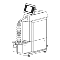
4 Place the drive/detector unit on a grinder machined block surface
(Ry ≦ 10 μm/393.700 μin).
5 Under this condition, check the stylus position display value in the Drive Unit
Operation screen is within ±30 μm (±1181.102 μin).
If the display value is less than -30 μm (-1181.102 μin), adjust the height of the
nosepiece.
• For information about adjusting the nosepiece height, refer to "3.3.4 Adjusting the
nosepiece height: for skid-attached measurement setup" (page 3-15).
If the display value is more than 30 μm (1181.102 μin), check for the following causes.
In these cases, check the zero point after resetting the stylus and nosepiece.
• Cause 1: There is a gap between the detector and nosepiece.
→ Reattach it so that no gap is created.
• Cause 2: The tip of the height adjustment screw is extruded above the nosepiece.
→ Adjust the tip so that it is not extruded above the nosepiece by adjusting the screw
position using an Allen wrench (nominal 0.9). Then reattach it.
• Cause 3: Combination of the stylus and nosepiece is not appropriate.
→ Use with a correct combination.
For causes other than those mentioned above, contact the dealer or a Mitutoyo sales
office.
• For information about attaching the stylus and nosepiece, refer to "3.2 Attaching a stylus
and a nosepiece" (page 3-2).
• For information about combination of stylus and nosepiece, refer to "22.8.2 Styli and
nosepiece" (page 22-11).
Grinder machined block surface
 Loading...