High-resolution timer (HRTIM) RM0440
1014/2126 RM0440 Rev 4
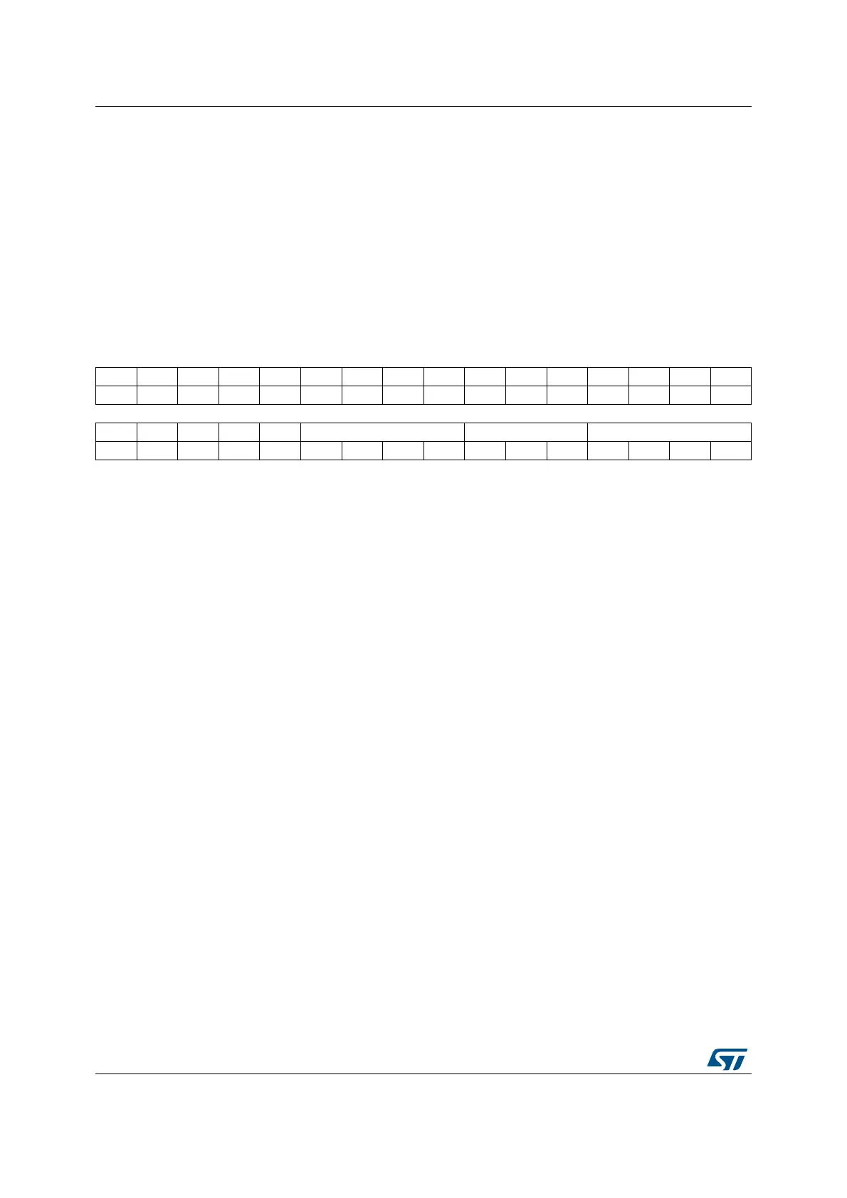
27.5.39 HRTIM timer x chopper register (HRTIM_CHPxR) (x = A to F)
Address offset: Block A: 0x0D8
Address offset: Block B: 0x158
Address offset: Block C: 0x1D8
Address offset: Block D: 0x258
Address offset: Block E: 0x2D8
Address offset: Block F: 0x358
Reset value: 0x0000 0000
31 30 29 28 27 26 25 24 23 22 21 20 19 18 17 16
Res. Res. Res. Res. Res. Res. Res. Res. Res. Res. Res. Res. Res. Res. Res. Res.
1514131211109876543210
Res. Res. Res. Res. Res. STRTPW[3:0] CARDTY[2:0 ) CARFRQ[3:0]
rw rw rw rw rw rw rw rw rw rw rw
Bits 31:11 Reserved, must be kept at reset value.
Bits 10:7 STRPW[3:0]: Timer x start pulsewidth
This register defines the initial pulsewidth following a rising edge on output signal.
This bitfield cannot be modified when one of the CHPx bits is set.
t
1STPW
= (STRPW[3:0]+1) x 16 x t
HRTIM
.
0000: 94.1 ns (1/10.625 MHz)
...
1111: 1.51 µs (16/10.625 MHz)
Bits 6:4 CARDTY[2:0]: Timer x chopper duty cycle value
This register defines the duty cycle of the carrier signal. This bitfield cannot be modified when one of
the CHPx bits is set.
000: 0/8 (i.e. only 1st pulse is present)
...
111: 7/8
Bits 3:0 CARFRQ[3:0]: Timer x carrier frequency value
This register defines the carrier frequency F
CHPFRQ
= f
HRTIM
/ (16 x (CARFRQ[3:0]+1)).
This bitfield cannot be modified when one of the CHPx bits is set.
0000: 10.625 MHz (f
HRTIM
/ 16)
...
1111: 664.1 kHz (f
HRTIM
/ 256)

 Loading...