RM0440 Rev 4 401/2126
RM0440 Peripherals interconnect matrix
401
11.3.10 From system errors to timers (TIMx) and HRTIM
TIMx (TIM1/TIM8/TIM20/TIM15/TIM16/TIM17) break inputs and HRTIM system fault input
gather MCU internal fault events coming from:
• the clock failure event generated by the clock security system (CSS),
• the PVD output,
• the SRAM parity error signal,
• the Cortex-M4 LOCKUP (Hardfault) output
• Flash ECC double error detection
The purpose of the break function is to protect power switches driven by PWM signals
generated by the timers.
The functionality is described in:
• Section 28.3.18: Using the break function (TIM1/TIM8/TIM20)
• Section 30.4.15: Using the break function (TIM15/TIM16/TIM17/TIM20)
Active power mode
Run, Sleep, Low-power run, Low-power sleep.
11.3.11 From timers (TIM16/TIM17) to IRTIM
General-purpose timer (TIM16/TIM17) output channel TIMx_OC1 are used to generate the
waveform of infrared signal output.
The functionality is described in Section 33: Infrared interface (IRTIM).
Active power mode
Run, Sleep, Low-power run, Low-power sleep.
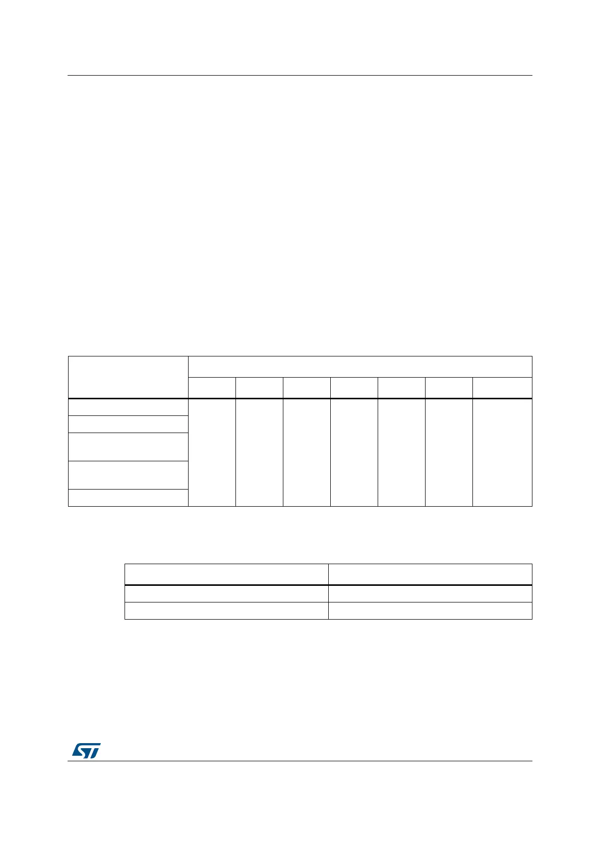
Table 83. Interconnect 18
System error signal surce
System error signals to timer signals assignment
TIM1 TIM8 TIM15 TIM16 TIM17 TIM20 HRTIM
Flash ECC error
tim1_bk tim8_bk tim15_bk tim16_bk tim17_bk tim20_bk hrtim_sys_flt
PVD output
SRAM1/
CCM SRAM parity
Cortex
®
-M4 Lockup
(hardfault)
Clock security system (CSS)
Table 84. Interconnect 16
IRTIM control signal IRTIM control signals assignment
modulation envelope signal tim16_oc1
carrier signal tim17_oc1
 Loading...


