Operational amplifiers (OPAMP) RM0440
794/2126 RM0440 Rev 4
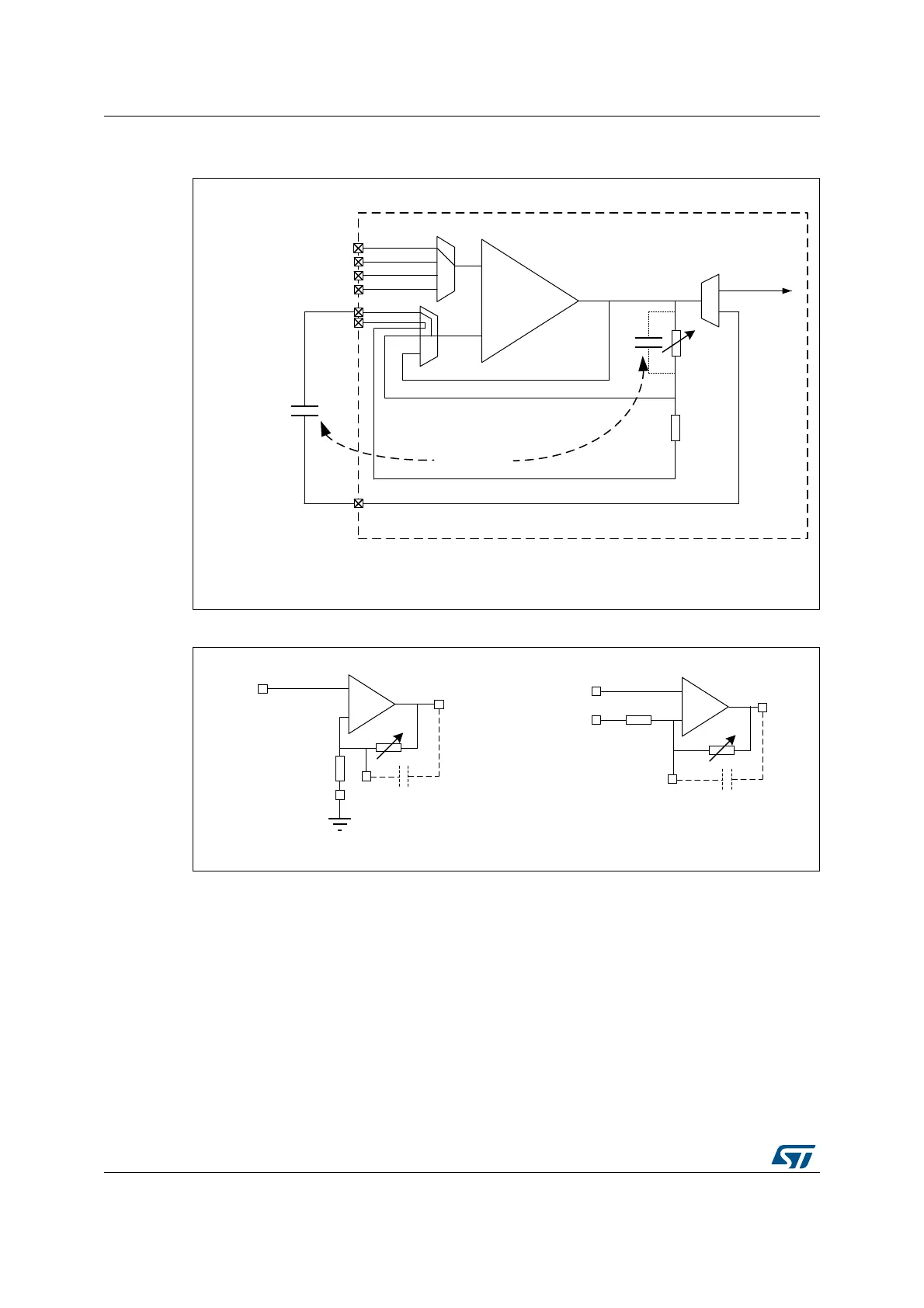
Figure 176. PGA mode, non-inverting gain setting (x2/x4/x8/x16/x32/x64)
or inverting gain setting (x-1/x-3/x-7/x-15/x-31/x-63) with filtering
Figure 177. Example configuration
25.3.6 OPAMP PGA gain
When the OPAMP is configured in PGA mode, the gain can be programmed to x2, x4, x8,
x16, x32, x64 in non-inverting configuration and x-1, x-3, x-7, x-15, x-31, x-63 for inverting
configuration.
When the OPAMP is configured in non-inverting mode, the gain solely depends on internal
resistive divider. When it is configured as inverting mode, Gain factor is defined not only the
on chip feedback resistor but also the signal source output impedance. If signal source
output impedance is not negligible compare to the input feedback resistance of PGA, it
creates the gain error.
STM32
+
-
VINM1
MSv48045V1
VOUT
Allows optional
low-pass
filtering
(1)
Equivalent to
VINM0
VINP4 or DACx_CHy
VINP2
VINP1
VINP0
1. opamp_out can be redirected internally to an ADC channel by setting OPAINTOEN bit.
In this case, the I/O on which is mapped the OPAMPx_VOUT is free and can be used for another purpose.
opamp_out
(1)
MSv48044V1
VINP
VINM0
+
-
Bias voltage
+
-
Bias voltage
Input signal
or
Gain:x2, x4, x8, x16, x32, x64 Gain:x-1, x-3, x-7, x-15
VINM1
VOUT
VINP
VINM1
VOUT
VINM0
 Loading...


