RM0440 Rev 4 1627/2126
RM0440 Universal synchronous/asynchronous receiver transmitter (USART/UART)
1733
37.5.17 USART Smartcard mode
This section is relevant only when Smartcard mode is supported. Refer to Section 37.4:
USART implementation on page 1595.
Smartcard mode is selected by setting the SCEN bit in the USART_CR3 register. In
Smartcard mode, the following bits must be kept cleared:
• LINEN bit in the USART_CR2 register,
• HDSEL and IREN bits in the USART_CR3 register.
The CLKEN bit can also be set to provide a clock to the Smartcard.
The Smartcard interface is designed to support asynchronous Smartcard protocol as
defined in the ISO 7816-3 standard. Both T=0 (character mode) and T=1 (block mode) are
supported.
The USART should be configured as:
• 8 bits plus parity: M=1 and PCE=1 in the USART_CR1 register
• 1.5 stop bits when transmitting and receiving data: STOP=’11’ in the USART_CR2
register. It is also possible to choose 0.5 stop bit for reception.
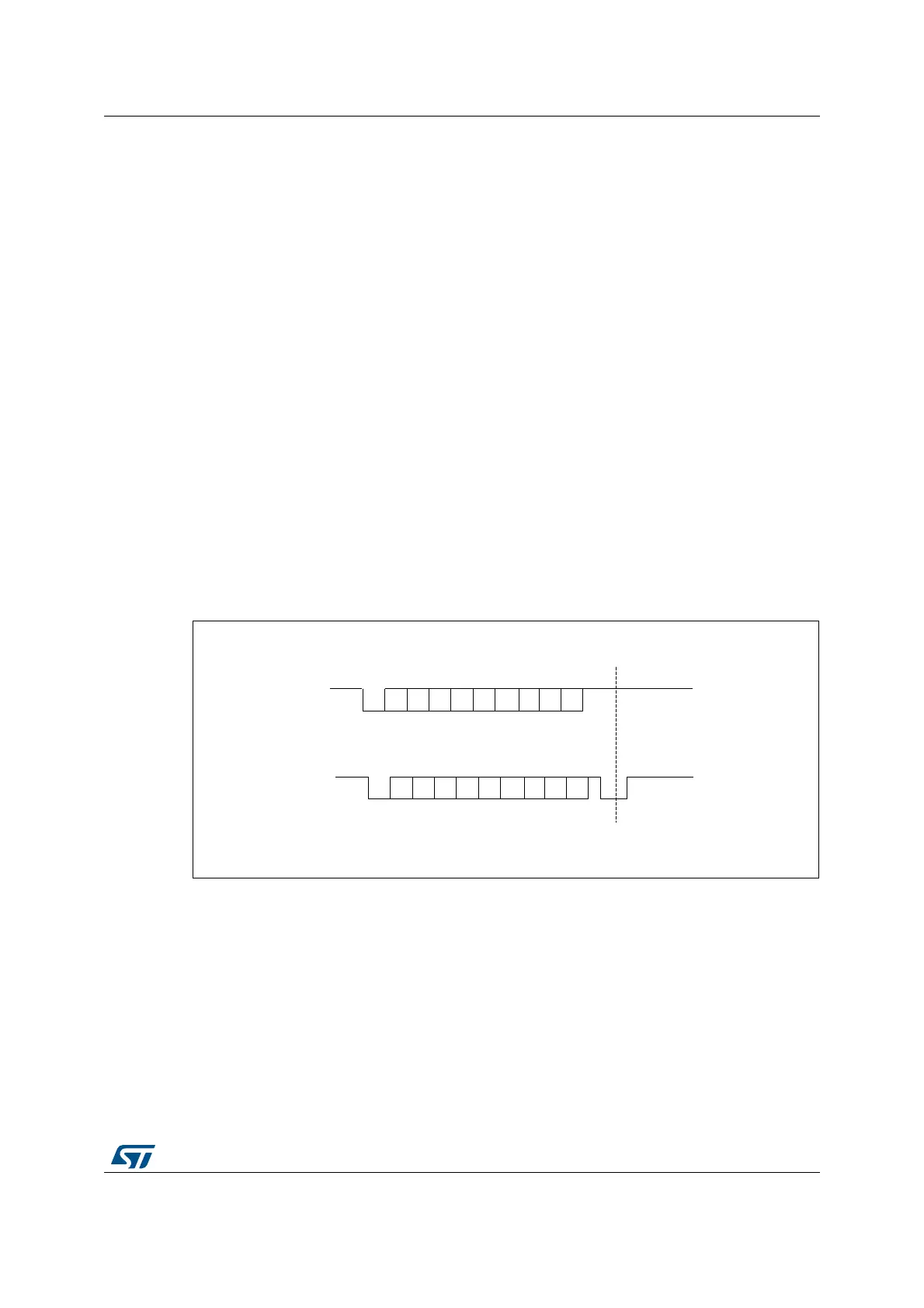
In T=0 (character) mode, the parity error is indicated at the end of each character during the
guard time period.
Figure 546 shows examples of what can be seen on the data line with and without parity
error.
Figure 546. ISO 7816-3 asynchronous protocol
When connected to a Smartcard, the TX output of the USART drives a bidirectional line that
is also driven by the Smartcard. The TX pin must be configured as open drain.
Smartcard mode implements a single wire half duplex communication protocol.
• Transmission of data from the transmit shift register is guaranteed to be delayed by a
minimum of 1/2 baud clock. In normal operation a full transmit shift register starts
shifting on the next baud clock edge. In Smartcard mode this transmission is further
delayed by a guaranteed 1/2 baud clock.
• In transmission, if the Smartcard detects a parity error, it signals this condition to the
USART by driving the line low (NACK). This NACK signal (pulling transmit line low for 1
baud clock) causes a framing error on the transmitter side (configured with 1.5 stop
bits). The USART can handle automatic re-sending of data according to the protocol.
MSv31162V1
Without Parity error
p
76543210S
Guard time
WithParity error
p
76543210S
Guard time
Start bit
Start bit
Line pulled low by receiver
during stop in case of parity error
 Loading...


