RM0440 Rev 4 1245/2126
RM0440 General-purpose timers (TIM2/TIM3/TIM4/TIM5)
1343
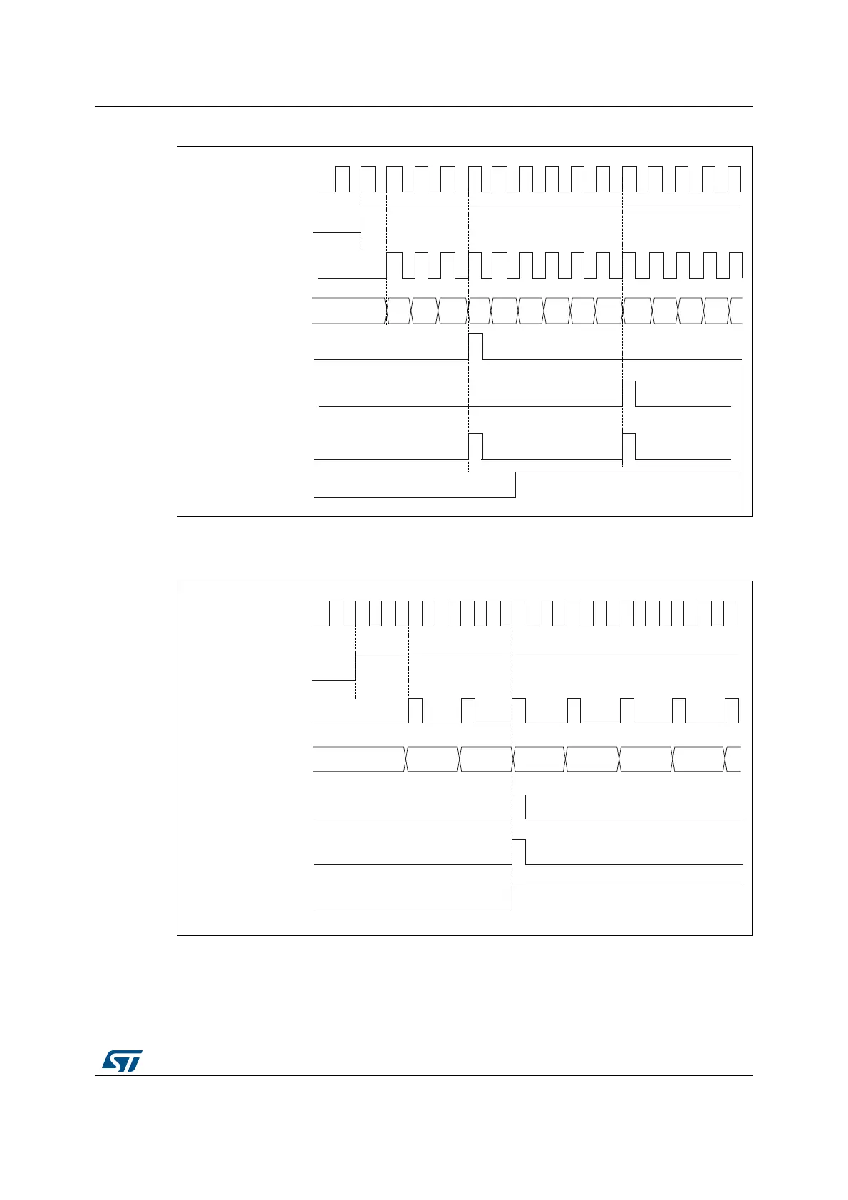
Figure 372. Counter timing diagram, internal clock divided by 1, TIMx_ARR=0x6
1. Here, center-aligned mode 1 is used (for more details refer to Section 29.5.1: TIMx control register 1
(TIMx_CR1)(x = 2 to 5) on page 1306).
Figure 373. Counter timing diagram, internal clock divided by 2
MSv62310V1
tim_psc_ck
tim_cnt_ck
Counter register
Update event (UEV)
Counter overflow
Update interrupt flag
(UIF)
00020304
05
06
01
CEN
02 03 0401 05 0304
Counter underflow
MSv62311V1
tim_psc_ck
CEN
tim_cnt_ck
Counter register
Update event (UEV)
Counter underflow
Update interrupt flag
(UIF)
0003
0002
0001
0000
0001
0002
0003
 Loading...


