Advanced-control timers (TIM1/TIM8/TIM20) RM0440
1142/2126 RM0440 Rev 4
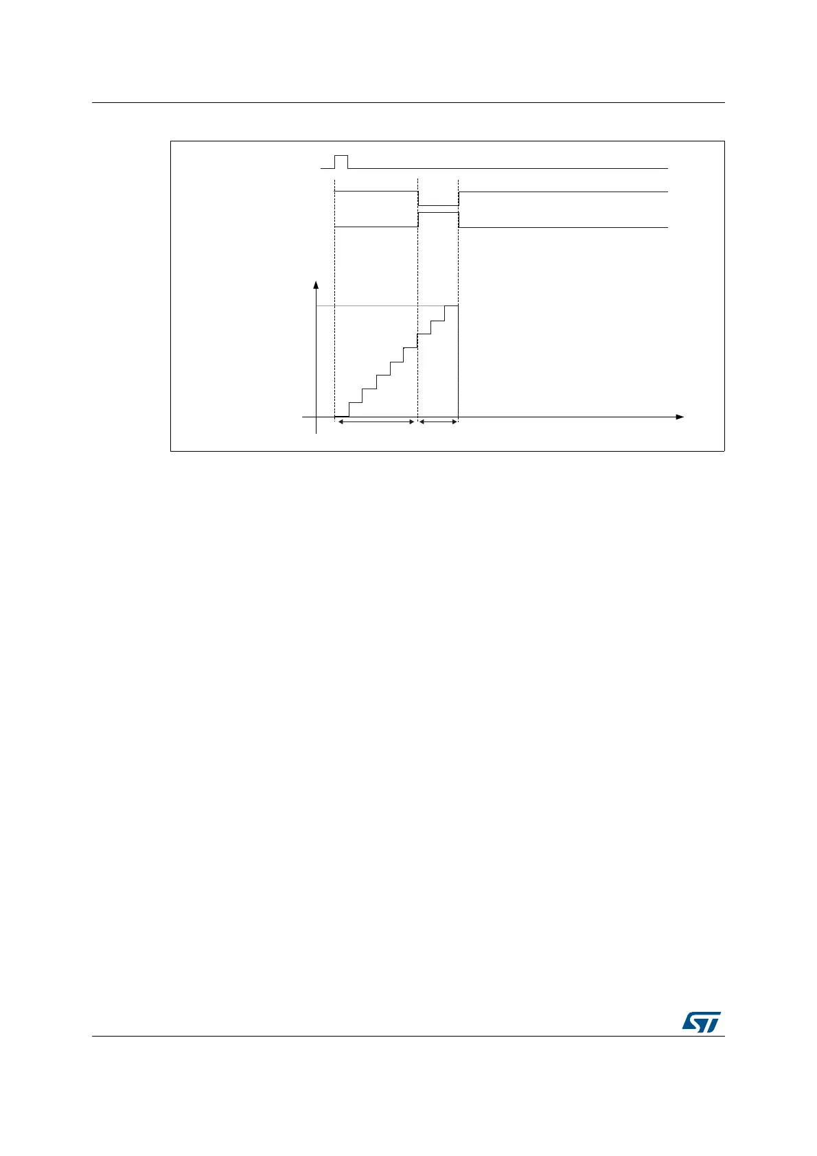
Figure 324. Example of one pulse mode.
For example one may want to generate a positive pulse on tim_oc1 with a length of t
PULSE
and after a delay of t
DELAY
as soon as a positive edge is detected on the tim_ti2 input pin.
Let’s use tim_ti2fp2 as trigger 1:
• Map tim_ti2fp2 to tim_ti2 by writing CC2S=’01’ in the TIMx_CCMR1 register.
• tim_ti2fp2 must detect a rising edge, write CC2P=’0’ and CC2NP=’0’ in the
TIMx_CCER register.
• Configure tim_ti2fp2 as trigger for the slave mode controller (tim_trgi) by writing
TS=00110 in the TIMx_SMCR register.
• tim_ti2fp2 is used to start the counter by writing SMS to ‘110’ in the TIMx_SMCR
register (trigger mode).
The OPM waveform is defined by writing the compare registers (taking into account the
clock frequency and the counter prescaler).
• The t
DELAY
is defined by the value written in the TIMx_CCR1 register.
• The t
PULSE
is defined by the difference between the auto-reload value and the compare
value (TIMx_ARR - TIMx_CCR1).
• Let’s say one want to build a waveform with a transition from ‘0’ to ‘1’ when a compare
match occurs and a transition from ‘1’ to ‘0’ when the counter reaches the auto-reload
value. To do this PWM mode 2 must be enabled by writing OC1M=111 in the
TIMx_CCMR1 register. Optionally the preload registers can be enabled by writing
OC1PE=’1’ in the TIMx_CCMR1 register and ARPE in the TIMx_CR1 register. In this
case one has to write the compare value in the TIMx_CCR1 register, the auto-reload
value in the TIMx_ARR register, generate an update by setting the UG bit and wait for
external trigger event on tim_ti2. CC1P is written to ‘0’ in this example.
In our example, the DIR and CMS bits in the TIMx_CR1 register should be low.
Since only 1 pulse (Single mode) is needed, a 1 must be written in the OPM bit in the
TIMx_CR1 register to stop the counter at the next update event (when the counter rolls over
from the auto-reload value back to 0). When OPM bit in the TIMx_CR1 register is set to '0',
so the Repetitive Mode is selected.
MSv62344V1
tim_ti2
tim_oc1ref
Counter
t
0
TIM1_ARR
TIM1_CCR1
tim_oc1
t
DELAY
t
PULSE
 Loading...


