RM0440 Rev 4 1821/2126
RM0440 Serial audio interface (SAI)
1858
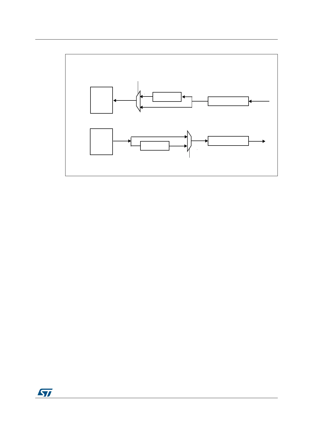
Figure 624. Data companding hardware in an audio block in the SAI
1. Not applicable when AC’97 or SPDIF are selected.
Expansion and compression mode are automatically selected through the SAI_xCR2:
• If the SAI audio block is configured to be a transmitter, and if the COMP[1] bit is set in
the SAI_xCR2 register, the compression mode will be applied.
• If the SAI audio block is declared as a receiver, the expansion algorithm will be applied.
Output data line management on an inactive slot
In transmitter mode, it is possible to choose the behavior of the SD line output when an
inactive slot is sent on the data line (via TRIS bit).
• Either the SAI forces 0 on the SD output line when an inactive slot is transmitted, or
• The line is released in HI-z state at the end of the last bit of data transferred, to release
the line for other transmitters connected to this node.
It is important to note that the two transmitters cannot attempt to drive the same SD output
pin simultaneously, which could result in a short circuit. To ensure a gap between
transmissions, if the data is lower than 32-bit, the data can be extended to 32-bit by setting
bit SLOTSZ[1:0] = 10 in the SAI_xSLOTR register. The SD output pin will then be tri-stated
at the end of the LSB of the active slot (during the padding to 0 phase to extend the data to
32-bit) if the following slot is declared inactive.
In addition, if the number of slots multiplied by the slot size is lower than the frame length,
the SD output line will be tri-stated when the padding to 0 is done to complete the audio
frame.
Figure 625 illustrates these behaviors.
expand
FIFO
COMP[1]
COMP[1]
32-bit shift register
SD
Receiver mode (bit MODE[0] = 1 in SAI_xCR1)
Transmitter mode (bit MODE[0] = 0 in SAI_xCR1)
MS19244V1
1
0
1
0
32-bit shift register
SD
compress
FIFO
 Loading...


