RM0440 Rev 4 261/2126
RM0440 Power control (PWR)
271
6.4.7 Power status clear register (PWR_SCR)
Address offset: 0x18
Reset value: 0x0000 0000.
Access: 3 additional APB cycles are needed to write this register vs. a standard APB write.
Bit 9 REGLPF: Low-power regulator flag
This bit is set by hardware when the MCU is in Low-power run mode. When the MCU exits
the Low-power run mode, this bit remains at 1 until the regulator is ready in main mode. A
polling on this bit must be done before increasing the product frequency.
This bit is cleared by hardware when the regulator is ready.
0: The regulator is ready in main mode (MR)
1: The regulator is in low-power mode (LPR)
Bit 8 REGLPS: Low-power regulator started
This bit provides the information whether the low-power regulator is ready after a power-on
reset or a Standby/Shutdown. If the Standby mode is entered while REGLPS bit is still
cleared, the wakeup from Standby mode time may be increased.
0: The low-power regulator is not ready
1: The low-power regulator is ready
Bit 7 FLASH_RDY: Flash ready flag
This bit is set by hardware to indicate when the Flash memory is ready to be accessed after
wakeup from power-down. To place the Flash memory in power-down, set either
FPD_LPRUN, FPD_LPSLP or FPD_STP bits.
0: Flash memory in power-down
1: Flash memory ready to be accessed
Note: If the system boots from SRAM, the user application must wait till FLASH_RDY bit is
set, prior to jumping to Flash memory.
Bits 6:0 Reserved, must be kept at reset value.
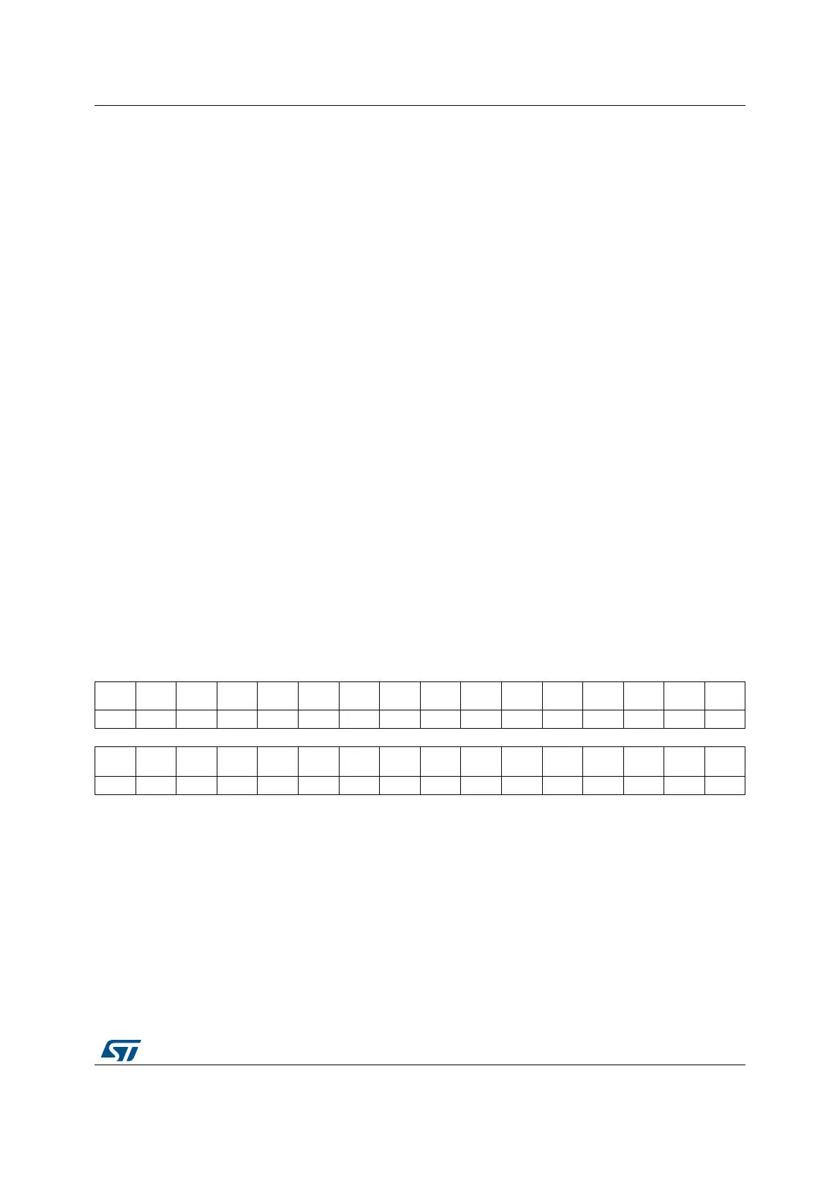
31 30 29 28 27 26 25 24 23 22 21 20 19 18 17 16
Res. Res. Res. Res. Res. Res. Res. Res. Res. Res. Res. Res. Res. Res. Res. Res.
1514131211109876543210
Res. Res. Res. Res. Res. Res. Res. CSBF Res. Res. Res.
CWUF
5
CWUF
4
CWUF
3
CWUF
2
CWUF
1
w wwwww
Bits 31:9 Reserved, must be kept at reset value.
Bit 8 CSBF: Clear standby flag
Setting this bit clears the SBF flag in the PWR_SR1 register.
Bits 7:5 Reserved, must be kept at reset value.
Bit 4 CWUF5: Clear wakeup flag 5
Setting this bit clears the WUF5 flag in the PWR_SR1 register.
Bit 3 CWUF4: Clear wakeup flag 4
Setting this bit clears the WUF4 flag in the PWR_SR1 register.