RM0440 Rev 4 789/2126
RM0440 Operational amplifiers (OPAMP)
829
25.3.5 OPAMP modes
The operational amplifier inputs and outputs are all accessible on terminals. The amplifiers
can be used in multiple configuration environments:
• Standalone mode (external gain setting mode)
• Follower configuration mode
• PGA modes
Note: The impedance of the signal must be maintained below a level which avoids the input
leakage to create significant artifacts (due to a resistive drop in the source). Please refer to
the electrical characteristics section in the datasheet for further details.
Standalone mode (external gain setting mode)
The procedure to use the OPAMP in standalone mode is presented hereafter.
Starting from the default value of OPAMPx_CSR, and the default state of GPIOx_MODER,
as soon as the OPAEN bit is set, the two input pins and the output pin are connected to the
operational amplifier.
This default configuration uses the factory trimming values and operates in normal mode
(highest performance). The behavior of the OPAMP can be changed as follows:
• OPAHSM can be set to “operational amplifier high-speed” mode in order to have high
slew rate.
• USERTRIM can be set to modify the trimming values for input offsets.
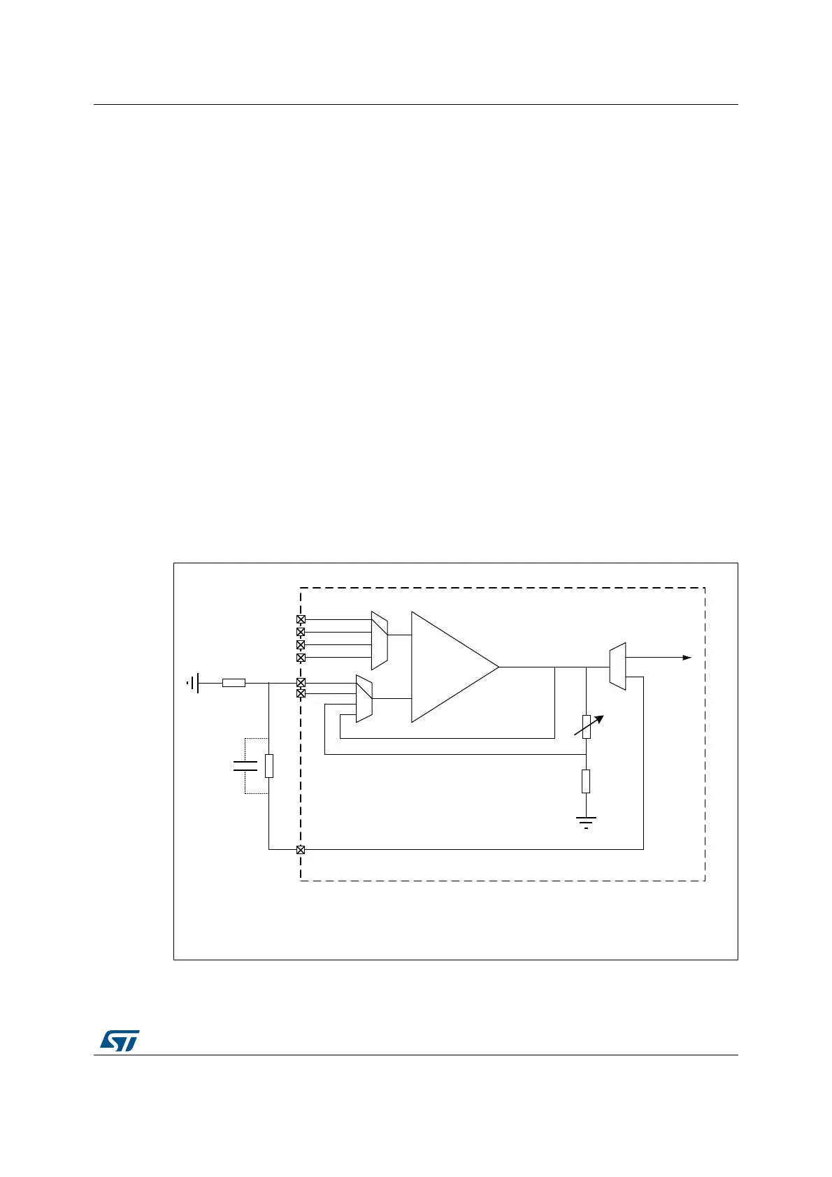
Figure 171. Standalone mode: external gain setting mode
STM32
+
-
INM0
INM1
opamp_out
(1)
MSv48039V1
VOUT
VINP3 or DACx_CHy
VINP2
VINP1
VINP0
1. opamp_out can be redirected internally to an ADC channel by setting OPAINTOEN bit.
In this case, the I/O on which is mapped the OPAMPx_VOUT is free and can be used for another purpose.
 Loading...


