Advanced-control timers (TIM1/TIM8/TIM20) RM0440
1154/2126 RM0440 Rev 4
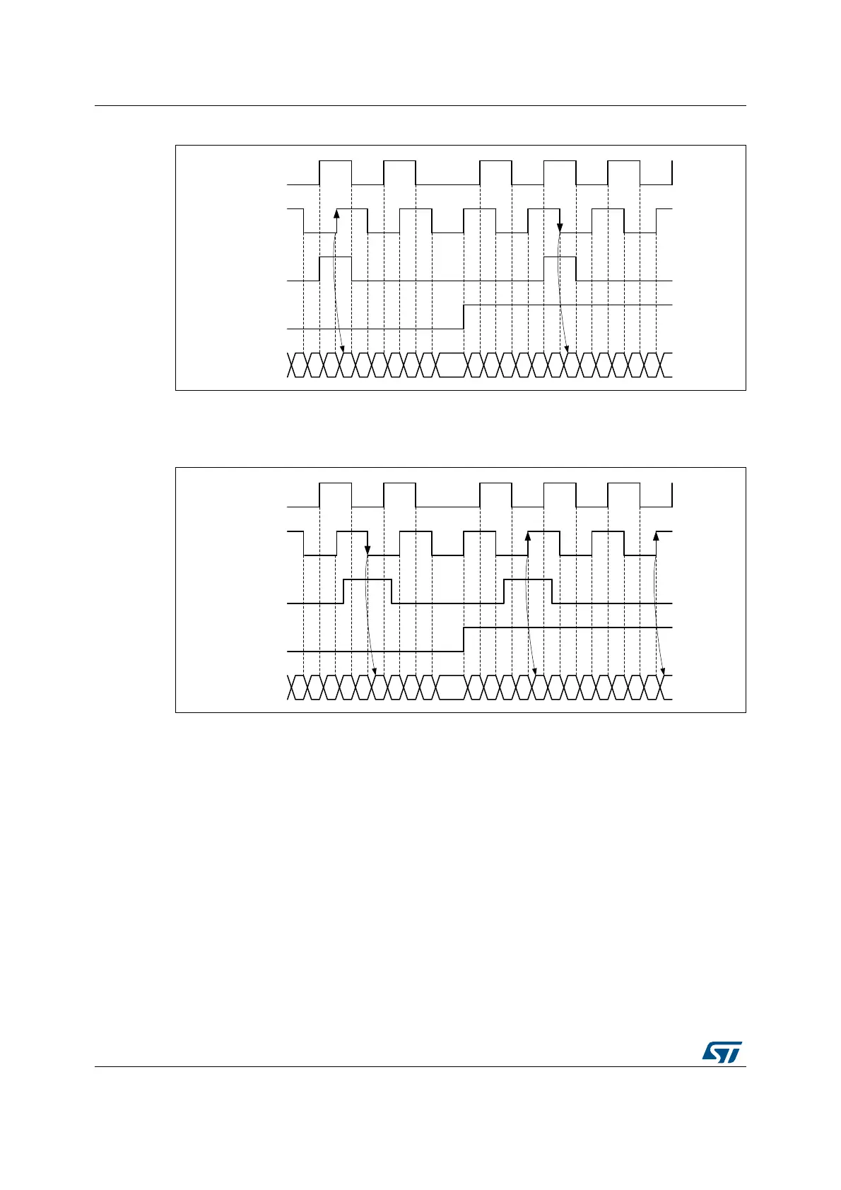
Figure 338. Counter reading with index gated on channel A (IPOS[1:0] = 11)
The Figure 339. below presents waveforms and corresponding values for the ungated
mode. The arrows are indicating on which transition is the index event generated.
Figure 339. Counter reading with index ungated (IPOS[1:0] = 00)
The Figure 340. below shows how the ‘gated on A & B’ mode is handled, for various pulse
alignment scenario. The arrows are indicating on which transition is the index event
generated.
MSv45768V1
Channel A
Channel B
DIR bit
Index
Counter 5 6 7 0 1 2 3 4 5 6 5 4 3 2 1 0 7 6 5 4 3 2 1
MSv45769V1
Channel A
Channel B
DIR bit
Index
Counter 3 4 5 6 7 0 1 2 3 4 3 2 1 0 7 6 5 4 3 2 1 0 7
 Loading...


