Analog-to-digital converters (ADC) RM0440
658/2126 RM0440 Rev 4
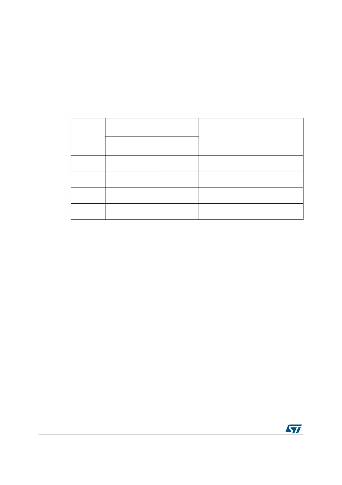
These thresholds are programmed in bits HT1[11:0] and LT1[11:0] of the ADC_TR1 register
for the analog watchdog 1. When converting data with a resolution of less than 12 bits
(according to bits RES[1:0]), the LSB of the programmed thresholds must be kept cleared
because the internal comparison is always performed on the full 12-bit raw converted data
(left aligned).
Table 170 describes how the comparison is performed for all the possible resolutions for
analog watchdog 1.
Analog watchdog filter for watchdog 1
When an ADC is configured with only one input channel (selecting several channels in Scan
mode not allowed), a valid ADC conversion data interval can be configured through the
ADC_TR1 register:
• When converted data belong to the interval defined in ADC_TR1, a DMA request is
generated.
• Otherwise, no DMA request is issued. RDATA register is updated at each conversion. If
data are out-of-range a number of times higher than the value specified in AWDFILT bit
of ADC_TR1, the AWDx flag is set an the corresponding interrupt is issued.
Description of analog watchdog 2 and 3
The second and third analog watchdogs are more flexible and can guard several selected
channels by programming the corresponding bits in AWDxCH[18:0] (x=2,3).
The corresponding watchdog is enabled when any bit of AWDxCH[18:0] (x=2,3) is set.
They are limited to a resolution of 8 bits and only the 8 MSBs of the thresholds can be
programmed into HTx[7:0] and LTx[7:0]. Table 171 describes how the comparison is
performed for all the possible resolutions.
Table 170. Analog watchdog 1 comparison
Resolution(
bit
RES[1:0])
Analog watchdog comparison
between:
Comments
Raw converted data,
left aligned
(1)
1. Refer to Section : Gain compensation for additional details on analog watchdog comparison.
Thresholds
00: 12-bit DATA[11:0]
LT1[11:0] and
HT1[11:0]
-
01: 10-bit DATA[11:2],00
LT1[11:0] and
HT1[11:0]
User must configure LT1[1:0] and HT1[1:0]
to 00
10: 8-bit DATA[11:4],0000
LT1[11:0] and
HT1[11:0]
User must configure LT1[3:0] and HT1[3:0]
to 0000
11: 6-bit DATA[11:6],000000
LT1[11:0] and
HT1[11:0]
User must configure LT1[5:0] and HT1[5:0]
to 000000
 Loading...


