General-purpose timers (TIM15/TIM16/TIM17) RM0440
1360/2126 RM0440 Rev 4
1. Select the proper tim_ti2_in[0..15] source (internal or external) with the TI2SEL[3:0] bits
in the TIMx_TISEL register.
2. Configure channel 2 to detect rising edges on the tim_ti2 input by writing CC2S = ‘01’ in
the TIMx_CCMR1 register.
3. Configure the input filter duration by writing the IC2F[3:0] bits in the TIMx_CCMR1
register (if no filter is needed, keep IC2F=0000).
4. Select rising edge polarity by writing CC2P=0 in the TIMx_CCER register.
5. Configure the timer in external clock mode 1 by writing SMS=111 in the TIMx_SMCR
register.
6. Select tim_ti2 as the trigger input source by writing TS=00110 in the TIMx_SMCR
register.
7. Enable the counter by writing CEN=1 in the TIMx_CR1 register.
Note: The capture prescaler is not used for triggering, it is not necessary to configure it.
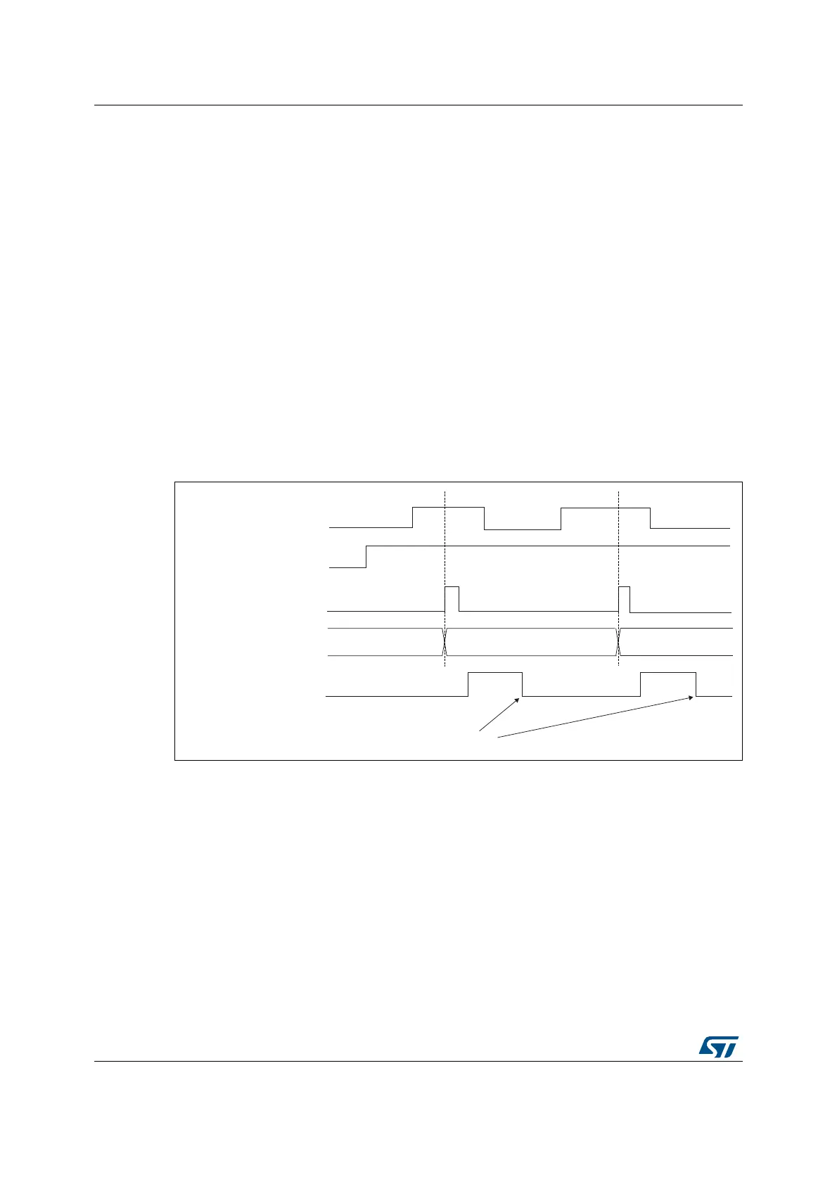
When a rising edge occurs on tim_ti2, the counter counts once and the TIF flag is set.
The delay between the rising edge on tim_ti2 and the actual clock of the counter is due to
the resynchronization circuit on tim_ti2 input.
Figure 452. Control circuit in external clock mode 1
30.4.7 Capture/compare channels
Each Capture/Compare channel is built around a capture/compare register (including a
shadow register), a input stage for capture (with digital filter, multiplexing and prescaler) and
an output stage (with comparator and output control).
Figure 453 to Figure 456 give an overview of one Capture/Compare channel.
The input stage samples the corresponding tim_tix input to generate a filtered signal
tim_tixf. Then, an edge detector with polarity selection generates a signal (tim_tixfpy) which
can be used as trigger input by the slave mode controller or as the capture command. It is
prescaled before the capture register (ICxPS).
MSv62319V1
tim_cnt_ck, tim_psc_ck
Counter register
35 3634
tim_ti2
CEN
TIF
Write TIF=0
 Loading...


