Basic timers (TIM6/TIM7) RM0440
1448/2126 RM0440 Rev 4
31.3.3 TIM6/TIM7 clocks
The timer bus interface is clocked by the tim_pclk APB clock.
The counter clock tim_ker_ck is connected to the tim_pclk input.
The CEN (in the TIMx_CR1 register) and UG bits (in the TIMx_EGR register) are actual
control bits and can be changed only by software (except for UG that remains cleared
automatically). As soon as the CEN bit is written to 1, the prescaler is clocked by the internal
clock tim_ker_ck.
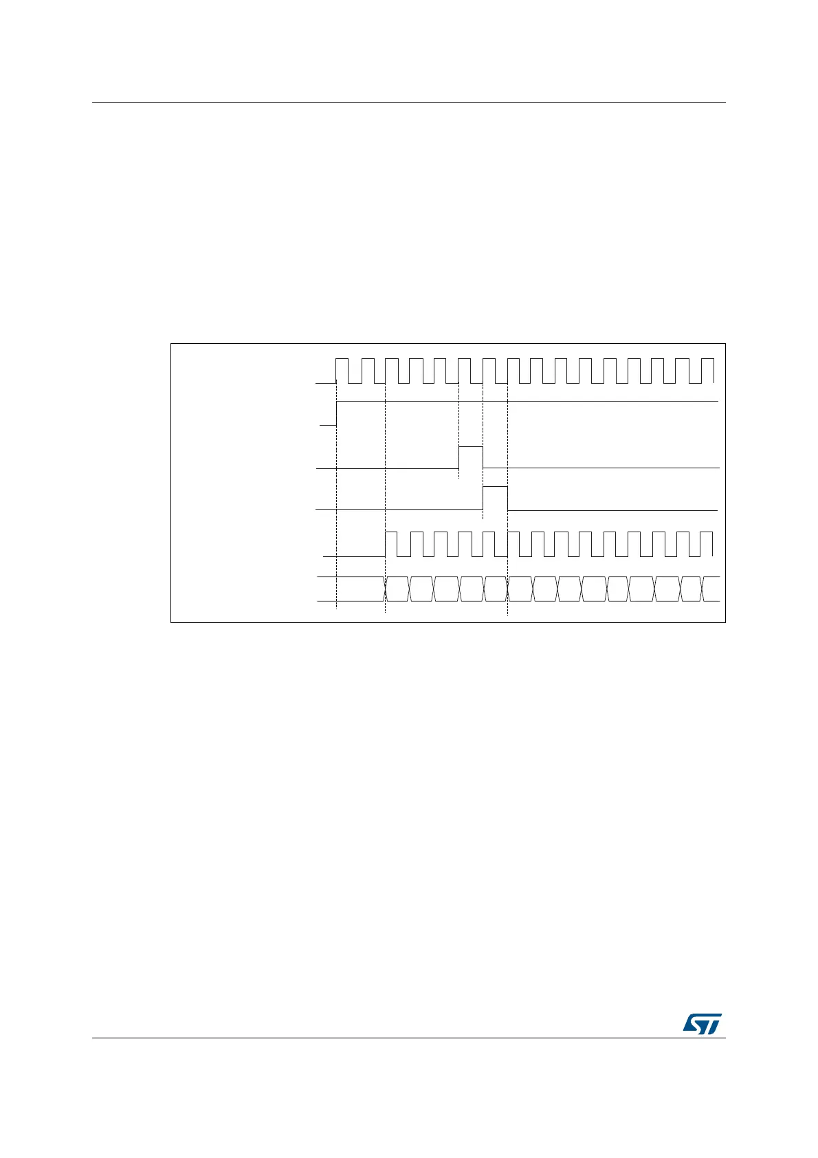
Figure 480 shows the behavior of the control circuit and the upcounter in normal mode,
without prescaler.
Figure 480. Control circuit in normal mode, internal clock divided by 1
31.3.4 Time-base unit
The main block of the programmable timer is a 16-bit upcounter with its related auto-reload
register. The counter clock can be divided by a prescaler.
The counter, the auto-reload register and the prescaler register can be written or read by
software. This is true even when the counter is running.
The time-base unit includes:
• Counter Register (TIMx_CNT)
• Prescaler Register (TIMx_PSC)
• Auto-Reload Register (TIMx_ARR)
The auto-reload register is preloaded. The preload register is accessed each time an
attempt is made to write or read the auto-reload register. The contents of the preload
register are transferred into the shadow register permanently or at each update event UEV,
depending on the auto-reload preload enable bit (ARPE) in the TIMx_CR1 register. The
update event is sent when the counter reaches the overflow value and if the UDIS bit equals
0 in the TIMx_CR1 register. It can also be generated by software. The generation of the
update event is described in detail for each configuration.
MSv62317V1
tim_ker_ck
tim_cnt_ck, tim_psc_ck
Counter register
CEN
UG
CNT_INIT
00
02
03
04 05
06 0732
33
34 35 36
31
01
 Loading...


