High-resolution timer (HRTIM) RM0440
928/2126 RM0440 Rev 4
The EEVx_muxout event mentioned in Table 233 above is taken after the hrtim_eevx[4:1]
input multiplexer controlled by the EExSRC[1:0]bits. Refer to Figure 216 for details.
The polarity of the signal can be selected to define the active level, using the FLTxP polarity
bit in HRTIM_FLTINRx registers. If FLTxP = 0, the signal is active at low level; if FLTxP = 1,
it is active when high.
The fault information can be filtered after the polarity setting. If FLTxF[3:0] bitfield is set to
0000, the signal is not filtered and acts asynchronously, independently from the
f
HRTIM
clock.
For all other FLTxF[3:0] bitfield values, the signal is digitally filtered. The digital filter is made
of a counter in which a number N of valid samples is needed to validate a transition on the
output. If the input value changes before the counter has reached the value N, the counter is
reset and the transition is discarded (considered as a spurious event). If the counter reaches
N, the transition is considered as valid and transmitted as a correct external event.
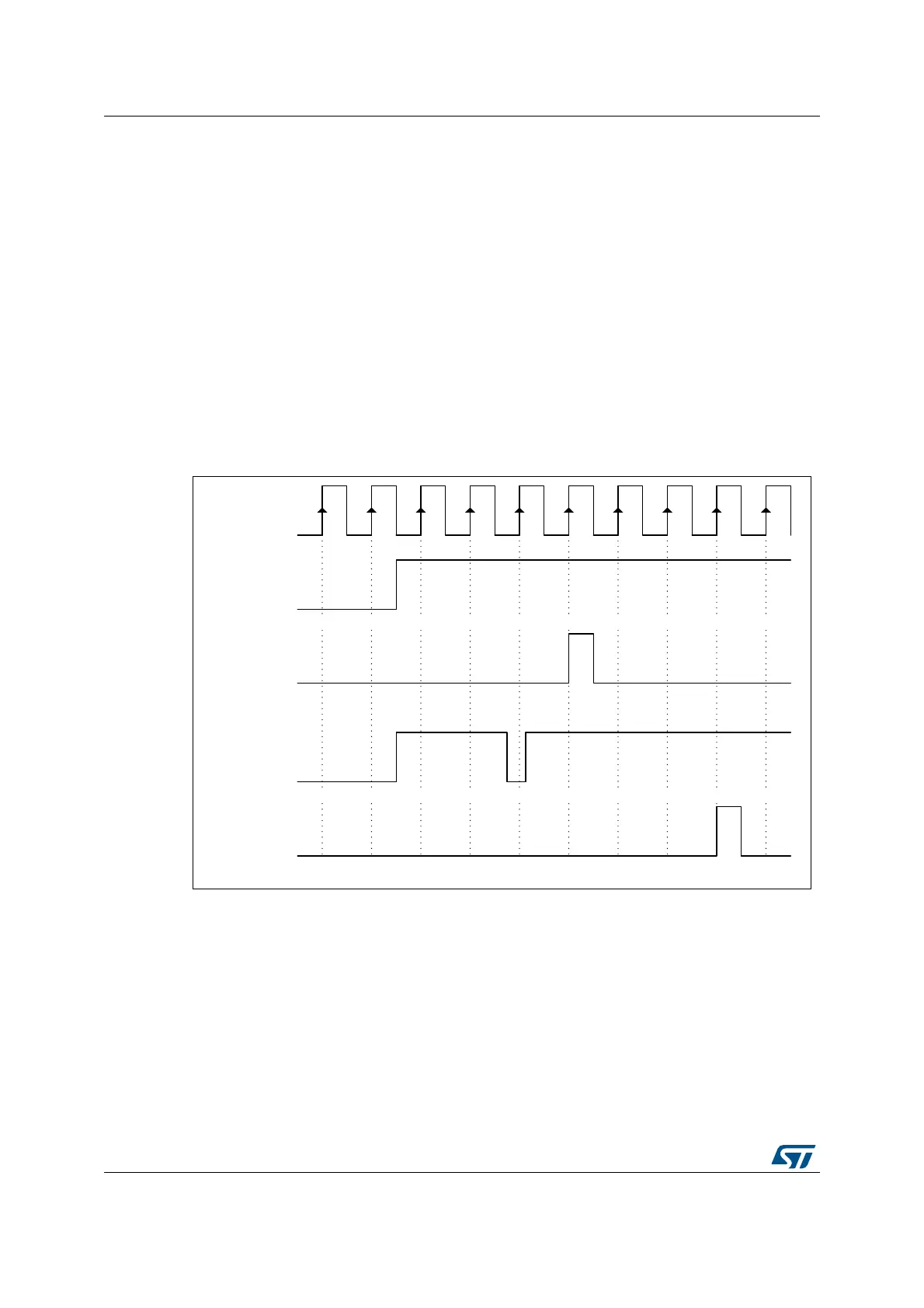
Consequently, the digital filter adds a latency to the external events being filtered,
depending on the sampling clock and on the filter length (number of valid samples
expected). Figure 245 shows how a spurious fault signal is filtered.
Figure 245. Fault signal filtering (FLTxF[3:0]= 0010: f
SAMPLING
= f
HRTIM
, N = 4)
The filtering period ranges from 2 cycles of the f
HRTIM
clock up to 8 cycles of the f
FLTS
clock
divided by 32. f
FLTS
is defined using FLTSD[1:0] bits in the HRTIM_FLTINR2 register.
Table 234 summarizes the sampling rate and the filter length. A jitter of 1 sampling clock
period must be subtracted from the filter length to take into account the uncertainty due to
the sampling and have the effective filtering.
MS32289V1
f
HRTIM
Fault input
Filtered signal
0 0 1 2 3 4 0 0 0 0
0 0 1 2 0 1 2 3 4 0
Filter counter
Fault input
Filtered signal
Filter counter
 Loading...


