Analog-to-digital converters (ADC) RM0440
646/2126 RM0440 Rev 4
21.4.26 Data management
Data register, data alignment and offset (ADC_DR, OFFSETy, OFFSETy_CH,
ALIGN)
Data and alignment
At the end of each regular conversion channel (when EOC event occurs), the result of the
converted data is stored into the ADC_DR data register which is 16 bits wide.
At the end of each injected conversion channel (when JEOC event occurs), the result of the
converted data is stored into the corresponding ADC_JDRy data register which is 16 bits
wide.
The ALIGN bit in the ADC_CFGR register selects the alignment of the data stored after
conversion. Data can be right- or left-aligned as shown in Figure 115, Figure 116, Figure 117
and Figure 118.
Special case: when left-aligned, the data are aligned on a half-word basis except when the
resolution is set to 6-bit. In that case, the data are aligned on a byte basis as shown in
Figure 117 and Figure 118.
Note: Left-alignment is not supported in oversampling mode. When ROVSE and/or JOVSE bit is
set, the ALIGN bit value is ignored and the ADC only provides right-aligned data.
Offset
An offset y (y=1,2,3,4) can be applied to a channel by setting the bit OFFSETy_EN=1 into
ADC_OFRy register. The channel to which the offset will be applied is programmed into the
bits OFFSETy_CH[4:0] of ADC_OFRy register. In this case, the converted value is
decreased by the user-defined offset written in the bits OFFSETy[11:0]. The result may be a
negative value so the read data is signed and the SEXT bit represents the extended sign
value.
Note: Offset correction is not supported in oversampling mode. When ROVSE and/or JOVSE bit is
set, the value of the OFFSETy_EN bit in ADC_OFRy register is ignored (considered as
reset).
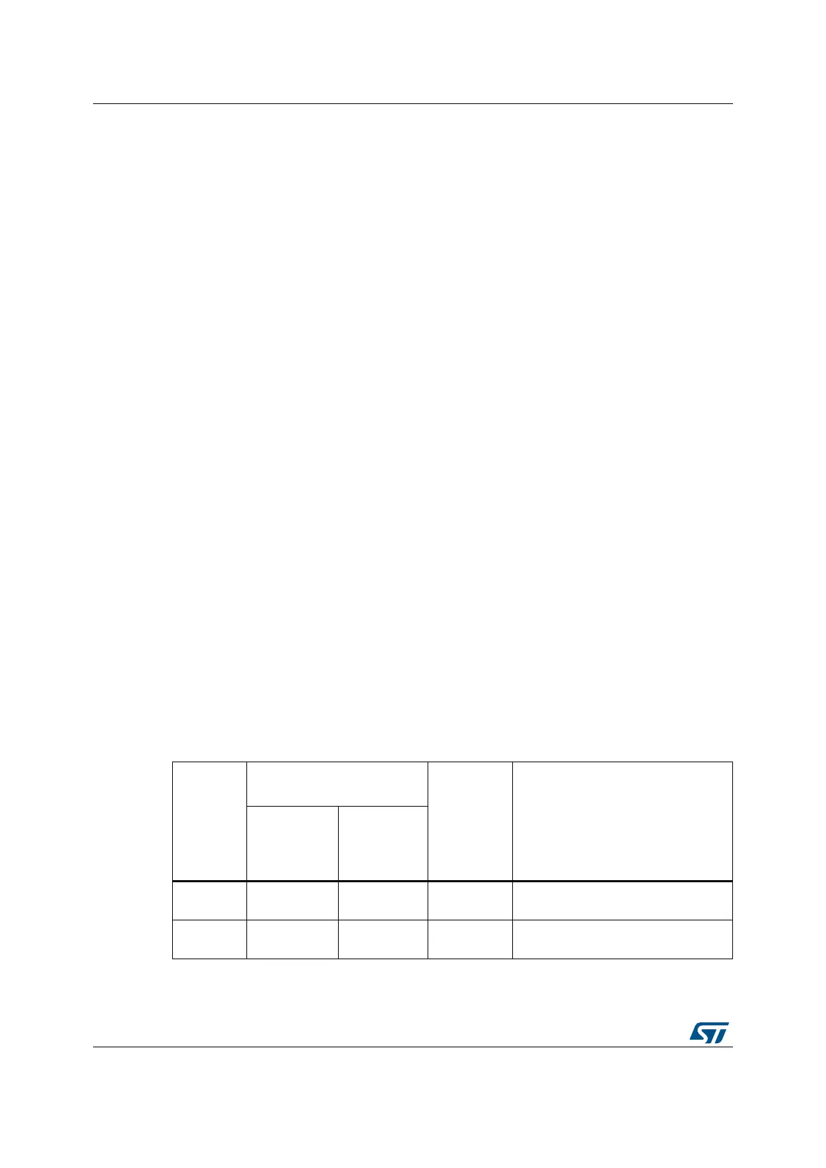
Table 170 describes how the comparison is performed for all the possible resolutions for
analog watchdog 1.
Table 168. Offset computation versus data resolution
Resolution
(bits
RES[1:0])
Subtraction between raw
converted data and offset
Result Comments
Raw
converted
Data, left
aligned
Offset
00: 12-bit DATA[11:0] OFFSET[11:0]
Signed
12-bit data
-
01: 10-bit DATA[11:2],00 OFFSET[11:0]
Signed
10-bit data
The user must configure OFFSET[1:0]
to “00”
 Loading...


