RM0440 Rev 4 1109/2126
RM0440 Advanced-control timers (TIM1/TIM8/TIM20)
1226
For example, to configure the upcounter to count in response to a rising edge on the tim_ti2
input, use the following procedure:
1. Configure channel 2 to detect rising edges on the tim_ti2 input by writing CC2S = ‘01’ in
the TIMx_CCMR1 register.
2. Configure the input filter duration by writing the IC2F[3:0] bits in the TIMx_CCMR1
register (if no filter is needed, keep IC2F=0000).
3. Select rising edge polarity by writing CC2P=0 and CC2NP=0 in the TIMx_CCER
register.
4. Configure the timer in external clock mode 1 by writing SMS=111 in the TIMx_SMCR
register.
5. Select tim_ti2 as the trigger input source by writing TS=00110 in the TIMx_SMCR
register.
6. Enable the counter by writing CEN=1 in the TIMx_CR1 register.
Note: The capture prescaler is not used for triggering, it is not necessary to configure it.
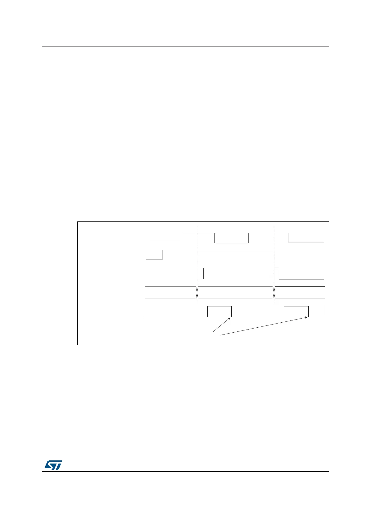
When a rising edge occurs on tim_ti2, the counter counts once and the TIF flag is set.
The delay between the rising edge on tim_ti2 and the actual clock of the counter is due to
the resynchronization circuit on tim_ti2 input.
Figure 293. Control circuit in external clock mode 1
External clock source mode 2
This mode is selected by writing ECE=1 in the TIMx_SMCR register.
The counter counts at each rising or falling edge on the external trigger input tim_etr_in.
The Figure 294 gives an overview of the external trigger input block.
MSv62319V1
tim_cnt_ck, tim_psc_ck
Counter register
35 3634
tim_ti2
CEN
TIF
Write TIF=0
 Loading...


