High-resolution timer (HRTIM) RM0440
864/2126 RM0440 Rev 4
Note: In half and interleaved modes, the compare registers are controlled by hardware and writing
them has no effect. However the written value is stored in the preload register and becomes
active on the update event following the exit of these modes.
Note: The triple and quad interleaved modes must not be used simultaneously with other modes
using CMP2 (dual channel dac trigger and triggered-half modes).
Null duty cycle exception case
The high-resolution behavior is not supported for pulses narrower than 3 t
HRTIM
periods
(see Section 27.3.7: Set / reset events priorities and narrow pulses management) and any
value strictly below 3 periods of the f
HRTIM
clock (that is 0x60 if CKPSC[2:0] = 0, 0x30 if
CKPSC[2:0] = 1, 0x18 if CKPSC[2:0] = 2,...) in the HRTIM_TIMxCMPy register is forbidden
(see 27.5.19: HRTIM timer x compare 1 register (HRTIM_CMP1xR) (x = A to F)).
However, it is possible to skip an output pulse and have a null duty cycle by simply writing a
null value in the following two registers: HRTIM_TIMxCMP1 and HRTIM_TIMxCMP3, if and
only if the following conditions are met:
– the output SET event is generated by the PERIOD event
– the output RESET if generated by the compare 1 (respectively compare 3) event
– the compare 1 (compare 3) event is active within the timer unit itself, and not used
for other timing units
For any other use case, this can be done by programming the SET and RESET events with
the very same compare values, above 3 periods of the f
HRTIM
clock. In this case, the output
is reset forced (following the set/reset priority scheme defined in the Section 27.3.7: Set /
reset events priorities and narrow pulses management).
Swap mode
This mode allows to swap the two outputs with a single bit access: the output 1 signal is
connected to the output 2 pin and the output 2 signal is connected to output 1 pin. The
output swap is triggered with the SWPx bits in the HRTIM_CR2 register and is effective on
the next update event.
The outputs are swapped prior to the set/reset crossbar unit, as following:
– if SWPx = 0, HRTIM_SETx1R and HRTIM_RSTx1R are coding for the output 1,
HRTIM_SETx2R and HRTIM_RSTx2R are coding for the output 2
– if SWPx = 1, HRTIM_SETx1R and HRTIM_RSTx1R are coding for the output 2,
HRTIM_SETx2R and HRTIM_RSTx2R are coding for the output 1
The swap mode is only affecting the preload register, and not the active registers.
Note: The preload mode must be enabled when using the swap mode.
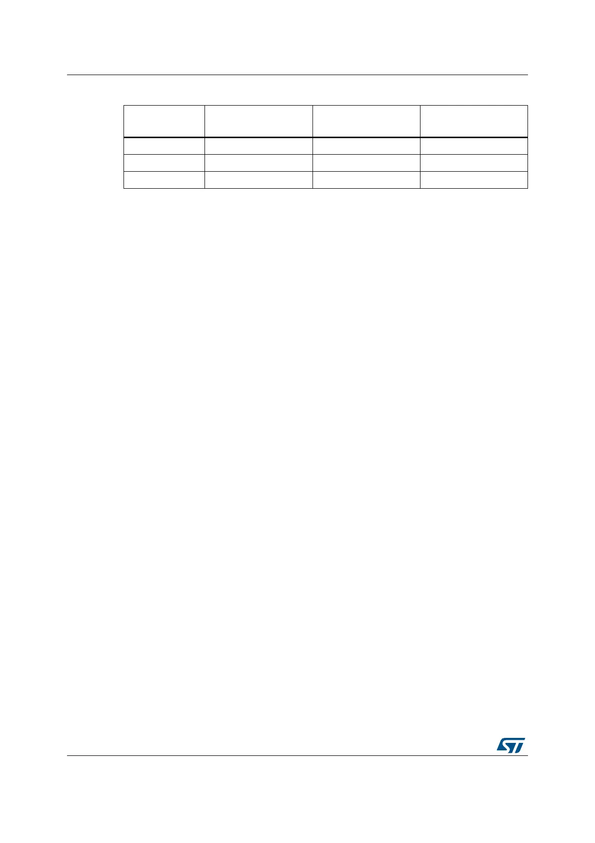
Table 218. Compare 1..3 values in interleaved mode
Mode
Dual interleaved
180°
Triple interleaved
120°
Quad interleaved
90°
CMP1 value PERxR/2 PERxR/3 PERxR/4
CMP2 value Not affected 2x (PERxR/3) PERxR/2
CMP3 value Not affected Not affected 3x (PERxR/4)
 Loading...


