Advanced-control timers (TIM1/TIM8/TIM20) RM0440
1108/2126 RM0440 Rev 4
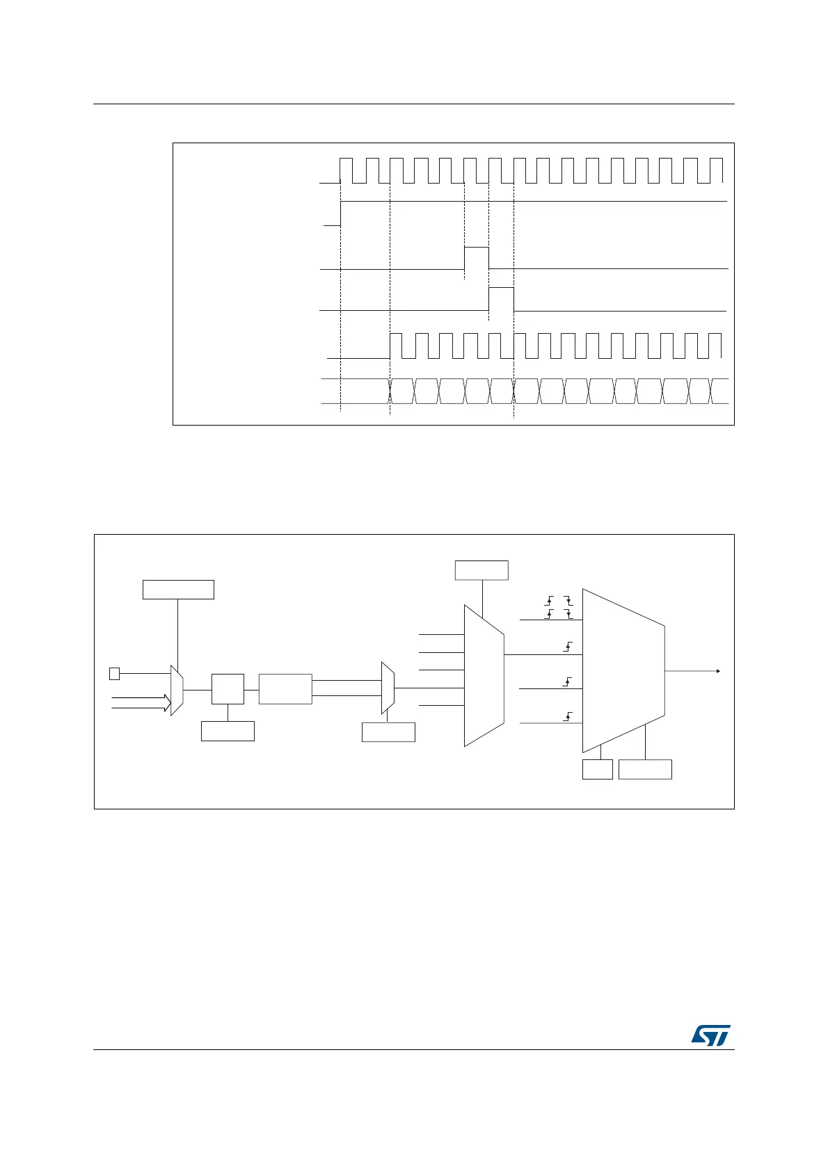
Figure 291. Control circuit in normal mode, internal clock divided by 1
External clock source mode 1
This mode is selected when SMS=111 in the TIMx_SMCR register. The counter can count at
each rising or falling edge on a selected input.
Figure 292. tim_ti2 external clock connection example
1. Codes ranging from 01000 to 11111 are reserved.
MSv62317V1
tim_ker_ck
tim_cnt_ck, tim_psc_ck
Counter register
CEN
UG
CNT_INIT
00
02
03
04 05
06 0732
33
34 35 36
31
01
MSv62318V1
External clock
mode 1
Internal clock
mode
tim_psc_ck
TIMx_SMCR
SMS[2:0]
tim_itrx
tim_ti1_ed
tim_ti1fp1
tim_ti2_fp2
TIMx_SMCR
TS[4:0]
tim_ti2_in0
0
1
TIMx_CCER
CC2P
TIMx_CCMR1
Edge
detector
tim_ti2f_rising
00110
000xx
00100
00101
Filter
ICF[3:0]
(internal clock)
Encoder
mode
etrf
00111
External clock
mode 2
ECE
tim_ti2
tim_trgi
tim_etrf
tim_ker_ck
tim_ti1f or
tim_ti2f or
or
TIM_CH2
(1)
TIMx_TISEL
TI2SEL[3:0]
tim_ti2_in[15..1]
tim_ti2f_failing
 Loading...


